
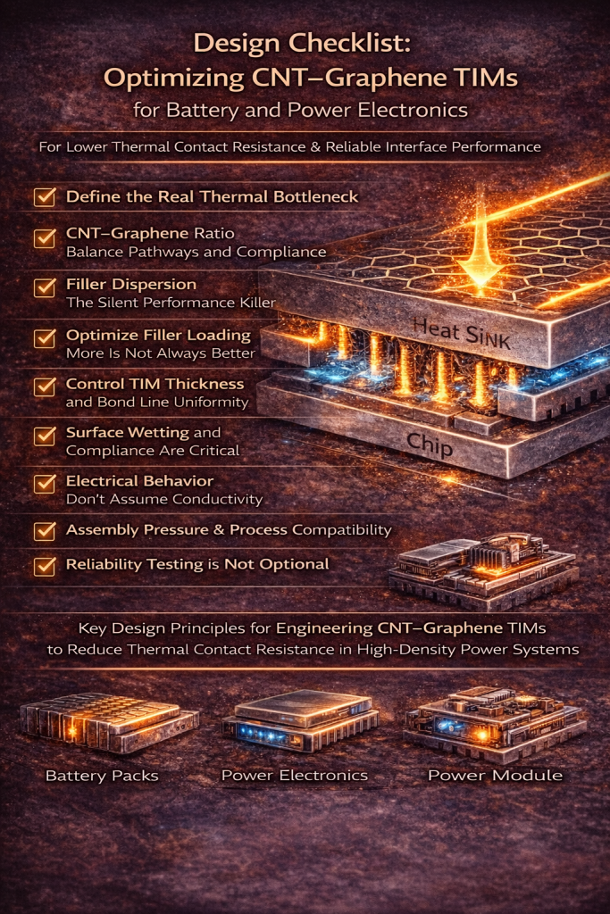
Design Checklist: Optimizing CNT–Graphene TIMs for Battery and Power Electronics
Why TIM Design Matters More Than Ever
As power density continues to rise in battery packs, inverters, DC–DC converters, and power modules, thermal interface materials (TIMs) are no longer passive fillers. They are now critical functional layers that directly influence:
-
Junction temperature
-
System reliability
-
Lifetime degradation
-
Safety margins
CNT–Graphene hybrid TIMs offer a unique combination of high intrinsic thermal conductivity, mechanical compliance, and percolated heat pathways.
However, performance is highly design-dependent.
This checklist walks through the key parameters engineers must optimize to translate material potential into real assembly performance.
1. Define the Real Thermal Bottleneck (Before Selecting Materials)
Before specifying any CNT–Graphene TIM, clarify:
✅ Is the bottleneck:
-
Bulk heat spreading?
-
Interfacial contact resistance?
-
Thickness constraints?
-
Mechanical compliance?
Key insight:
In most battery and power electronics assemblies, thermal contact resistance dominates, not the bulk thermal conductivity of the TIM.
👉 This directly affects filler selection, loading, and formulation strategy.
2. CNT–Graphene Ratio: Balance Pathways and Compliance
CNTs and graphene play different thermal roles:
| Filler | Primary Function |
|---|---|
| Graphene | In-plane heat spreading |
| CNTs | Through-plane bridging & gap filling |
Design checklist:
-
❏ Use graphene for lateral heat distribution
-
❏ Use CNTs to connect rough surfaces and micro-voids
-
❏ Avoid graphene-only systems in pressure-limited assemblies
-
❏ Avoid CNT-only systems where in-plane spreading is critical
Best practice:
Hybrid networks outperform single-filler systems at lower total filler loadings.
3. Filler Dispersion: The Silent Performance Killer
Poor dispersion leads to:
-
Agglomeration
-
Local hotspots
-
Increased interface resistance
Checklist:
-
❏ Ensure de-agglomeration during compounding
-
❏ Avoid CNT entanglement clusters
-
❏ Maintain graphene sheet integrity (avoid excessive shear)
-
❏ Verify dispersion with SEM or rheology trends
Engineering tip:
Uniform dispersion improves contact area utilization, often more impactful than increasing filler content.
4. Optimize Filler Loading (More Is Not Always Better)
High filler loading increases conductivity—but also:
-
Increases viscosity
-
Reduces wetting
-
Raises interface resistance
Target approach:
-
❏ Use percolation efficiency, not max loading
-
❏ Balance viscosity vs surface conformity
-
❏ Validate thermal resistance, not just W/m·K
Rule of thumb:
A TIM with lower bulk conductivity but better interface wetting often outperforms a stiffer, high-k alternative.
5. Control TIM Thickness and Bond Line Uniformity
Thermal resistance scales with thickness, not marketing specs.
Checklist:
-
❏ Minimize bond line thickness (BLT)
-
❏ Ensure uniform filler distribution at thin layers
-
❏ Avoid filler sedimentation during curing
-
❏ Match TIM rheology to application method
CNT advantage:
CNT networks remain effective even at ultra-thin BLTs, where plate-like fillers struggle to bridge gaps.
6. Surface Wetting and Compliance Are Critical
Real assemblies are never perfectly flat.
Design priorities:
-
❏ Low modulus for surface conformity
-
❏ CNT-assisted micro-gap filling
-
❏ Controlled curing shrinkage
-
❏ Stable contact under thermal cycling
Battery systems note:
Thermal cycling + vibration makes elastic recovery and adhesion stability just as important as conductivity.
7. Electrical Behavior: Don’t Assume Conductivity
CNT–Graphene systems can be:
-
Electrically conductive
-
Semi-conductive
-
Near-insulating (with proper design)
Checklist:
-
❏ Define electrical isolation requirements early
-
❏ Control CNT loading near percolation threshold
-
❏ Use surface-treated fillers when needed
-
❏ Validate volume resistivity after aging
8. Assembly Pressure & Process Compatibility
TIM performance depends heavily on applied pressure.
Checklist:
-
❏ Validate performance under real clamping force
-
❏ Avoid lab-only pressure conditions
-
❏ Match TIM rheology to dispensing or screen printing
-
❏ Consider reworkability for module repair
9. Reliability Testing Is Not Optional
CNT–Graphene TIMs must survive:
-
Thermal cycling
-
Power cycling
-
Humidity exposure
-
Long-term compression
Checklist:
-
❏ Measure thermal resistance before & after cycling
-
❏ Monitor pump-out and dry-out risks
-
❏ Validate adhesion to Al, Cu, and coated surfaces
-
❏ Test under real module geometry
10. Think System-Level, Not Material-Level
The best CNT–Graphene TIM is the one that:
-
Lowers junction temperature
-
Reduces thermal resistance stack
-
Maintains stable interfaces over time
Final takeaway:
TIM optimization is a system engineering problem, not a material spec competition.
Designing CNT–Graphene TIMs That Actually Work
CNT–Graphene hybrid TIMs unlock high-performance thermal pathways—but only when designed intentionally around:
-
Interfaces
-
Compliance
-
Dispersion
-
Assembly realities
For battery and power electronics engineers, success lies in reducing thermal resistance where it truly matters—at the interfaces.