

CNT Networks in Real Materials: Not Just Lab Data
Why Carbon Nanotube Performance Depends on More Than Just Numbers
Carbon nanotubes (CNTs) are often introduced with impressive numbers—ultra-high electrical conductivity, exceptional mechanical strength, and superior aspect ratios.
However, in real-world applications, many engineers quickly realize a key truth:
CNT performance in actual materials is not determined by intrinsic properties alone.
Instead, it depends on how effectively CNTs form networks inside real systems—under real processing conditions.
This article explores why CNT networks behave differently outside the lab, and what truly determines their performance in practical applications.
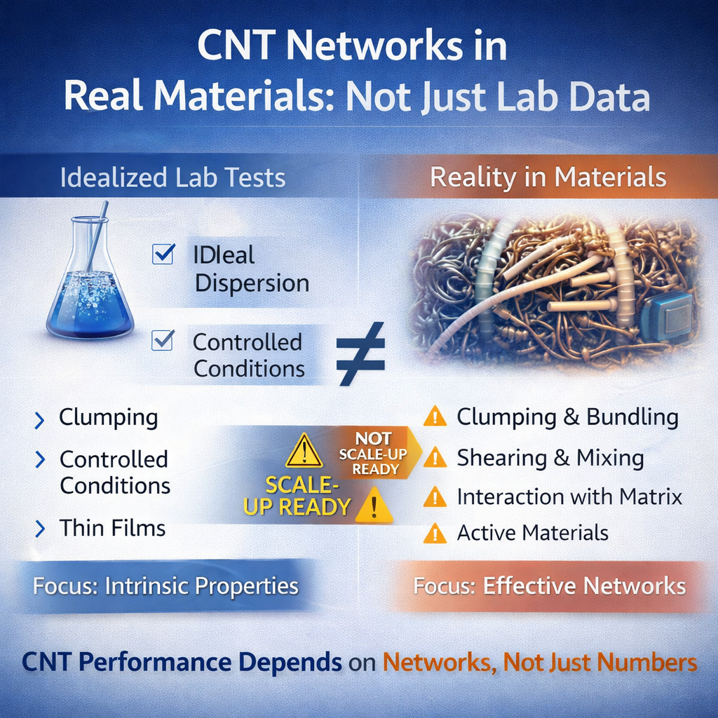
The Gap Between Lab Data and Real Materials
In research papers, CNTs are often evaluated under highly controlled conditions:
- Ideal dispersion
- Low impurity levels
- Optimized processing methods
- Thin film or simplified systems
Under these conditions, CNTs can demonstrate:
- Very high conductivity
- Low percolation thresholds
- Uniform network formation
But in real materials—such as coatings, polymers, electrodes, or composites—conditions are far more complex.
Real-World Factors That Change Everything
1. Dispersion Challenges
CNTs naturally tend to:
- Agglomerate
- Entangle
- Form bundles
In practical systems, achieving uniform dispersion is difficult.
Poor dispersion leads to:
- Reduced conductivity
- Inconsistent performance
- Local defects
2. Processing Constraints
Real manufacturing processes impose limitations such as:
- Shear forces (mixing, coating)
- Viscosity constraints
- Time and cost limitations
Unlike lab-scale methods, industrial processes cannot always maintain ideal CNT structures.
3. Interaction with Matrix Materials
CNTs do not exist alone—they are embedded in matrices such as:
- Polymers
- Resins
- Binders
- Electrochemical systems
The interaction between CNTs and the matrix affects:
- Network formation
- Electrical pathways
- Mechanical properties
Weak interaction can lead to:
- Poor load transfer
- Network instability
4. Loading vs Performance Trade-Off
In theory, CNTs can achieve conductivity at very low loading levels.
In reality:
- Too little → network not formed
- Too much → agglomeration, viscosity issues
Finding the optimal loading is a key engineering challenge.
What Is a “CNT Network” in Practice?
A CNT network is not just the presence of nanotubes—it is a continuous conductive pathway formed through:
- Physical contact
- Electron tunneling
- Interconnected structures
Key Characteristics of Effective Networks
Percolation Threshold
The minimum CNT content required to form a conductive network.
- Lab data: often very low
- Real systems: usually higher
Network Connectivity
How well CNTs connect with each other.
- Affects conductivity directly
- Depends on dispersion and processing
Stability
A good network must remain stable under:
- Mechanical stress
- Thermal cycling
- Long-term use
Why Lab Results Often Don’t Translate
Over-Optimized Conditions
Lab experiments may use:
- Ultrasonic dispersion
- Special surfactants
- Long processing times
These are not always scalable.
Simplified Systems
Many studies use:
- Thin films
- Single-material systems
Real products are multi-component systems with complex interactions.
Measurement Differences
Conductivity measured in:
- Ideal lab samples
≠ - Bulk industrial materials
CNT Networks in Key Applications
1. Conductive Coatings
Challenges:
- Maintaining dispersion during coating
- Avoiding re-agglomeration
Key factor:
👉 Network formation during drying process
2. Polymer Composites
Challenges:
- Mixing CNTs into viscous systems
- Balancing mechanical and electrical properties
Key factor:
👉 Shear-induced alignment vs network disruption
3. Battery Electrodes
Challenges:
- Interaction with active materials
- Maintaining conductive pathways during cycling
Key factor:
👉 Stable conductive network under electrochemical conditions
4. Thermal Interface Materials (TIMs)
Challenges:
- Contact resistance
- Integration with other fillers
Key factor:
👉 Hybrid network formation (CNT + graphene or other materials)
From “Material” to “System”
A common misunderstanding is:
“Better CNT = Better performance”
In reality:
Better network = Better performance
This shifts the focus from:
- Material specification
👉 to - System integration and processing
The Role of Hybrid Systems
In many real applications, CNTs are not used alone.
They are combined with:
- Graphene
- Carbon black
- Metal particles
Why Hybrid Networks Work Better
- CNTs provide long-range connectivity
- Graphene provides planar conduction
- Other fillers improve packing density
👉 Result: more robust and efficient conductive networks
Why Pilot Validation Matters
CNT performance must be validated under:
- Real mixing conditions
- Real coating or forming processes
- Real operating environments
Pilot lines help:
- Identify dispersion issues
- Optimize formulations
- Validate scalability
Without this step, many CNT-based solutions fail during scale-up.
What Customers Should Really Ask
Instead of asking:
- “What is the conductivity of your CNTs?”
A better question is:
- “How do your CNTs perform in my system?”
Even better:
- “Can you support validation at pilot scale?”
Carbon nanotubes offer extraordinary potential—but their real value lies not in isolated properties, but in how they form networks inside real materials.
The transition from lab data to industrial performance requires:
- Controlled dispersion
- Process-aware formulation
- System-level validation
In practical applications, success is not defined by the CNT itself, but by the network it creates—and the process that enables it.