
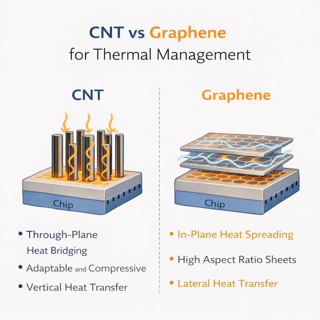
CNT vs Graphene for Thermal Management
Strengths, Limitations, and Application-Driven Choices
Carbon nanotubes (CNTs) and graphene are two of the most widely discussed nanocarbon materials for thermal management. Both offer exceptional intrinsic thermal conductivity, yet their real-world performance differs significantly once they are integrated into coatings, thermal interface materials (TIMs), or composite systems.
Understanding where each material excels—and where it falls short—is critical for making the right engineering choice.
This article compares CNTs and graphene from a practical thermal-engineering perspective, focusing on performance, processing, and application suitability.
1. Intrinsic Thermal Properties: Numbers vs Reality
| Material | Intrinsic Thermal Conductivity (Ideal) |
|---|---|
| Graphene (in-plane) | ~2000–5000 W/m·K |
| CNT (axial direction) | ~3000 W/m·K |
On paper, both materials appear outstanding.
In practice, however, intrinsic values rarely translate directly into system-level performance.
Why?
Because thermal management is not just about bulk conductivity—it is about:
-
Phonon transport continuity
-
Contact resistance
-
Network formation
-
Interface conformity
This is where CNTs and graphene begin to diverge.
2. Graphene: Strengths and Limitations
Key Strengths of Graphene
① Exceptional In-Plane Heat Spreading
Graphene’s 2D sheet structure enables extremely efficient lateral heat dissipation, making it ideal for:
-
Heat spreader coatings
-
EMI + thermal multifunctional layers
-
Large-area thermal films
② Barrier and Stability Benefits
Graphene layers can also provide:
-
Chemical resistance
-
Gas and moisture barrier properties
-
Improved coating durability
③ High Aspect Ratio (Lateral)
When aligned or well-dispersed, graphene forms conductive planes that efficiently redistribute heat across surfaces.
Limitations of Graphene in Thermal Interfaces
① Poor Through-Plane Conductivity
Heat transfer perpendicular to graphene sheets is significantly lower due to:
-
Weak interlayer coupling
-
Phonon scattering at sheet interfaces
② Interface Contact Challenges
Graphene sheets:
-
Do not naturally conform to surface roughness
-
Tend to restack or agglomerate
-
Create air gaps at real interfaces
③ Performance Highly Depends on Orientation
Without controlled alignment, much of graphene’s intrinsic advantage is lost in practical assemblies.
3. CNTs: Strengths and Limitations
Key Strengths of CNTs
① Excellent Through-Thickness Heat Pathways
CNTs form 1D conductive bridges, allowing heat to move efficiently:
-
Across interfaces
-
Between uneven or rough surfaces
This makes CNTs particularly effective in:
-
Thermal interface materials (TIMs)
-
Gap fillers
-
Vertically conductive composites
② High Compliance and Conformability
CNT networks can:
-
Compress under low pressure
-
Adapt to surface irregularities
-
Reduce thermal contact resistance (TCR)
③ Robust Percolation Networks
Even at relatively low loadings, CNTs can form continuous heat-conducting pathways.
Limitations of CNTs
① Lower In-Plane Heat Spreading
Compared to graphene sheets, CNTs are less effective at lateral heat distribution.
② Dispersion and Cost Challenges
-
CNT dispersion requires careful processing
-
High-purity CNTs can be cost-intensive
-
Agglomeration affects consistency if not controlled
③ Limited Barrier or Structural Effects
CNTs provide less benefit in terms of corrosion resistance or barrier properties compared to graphene.
4. CNT vs Graphene: Application-Oriented Comparison
| Application | Better Choice | Reason |
|---|---|---|
| Thermal Interface Materials (TIMs) | CNT | Lower contact resistance, vertical pathways |
| Gap fillers / compressible pads | CNT | Compliance and surface conformity |
| Heat spreader coatings | Graphene | Superior in-plane conductivity |
| EMI + thermal coatings | Graphene | Sheet structure + conductivity |
| Thin interfaces (<100 μm) | CNT–Graphene hybrid | Balanced conduction + interface control |
| Battery modules | Hybrid | Interface + spreading both matter |
5. Why Hybrid CNT–Graphene Systems Are Emerging
In real assemblies, no single material solves all thermal challenges.
Hybrid CNT–graphene systems combine:
-
CNTs for vertical heat transfer and interface bridging
-
Graphene for lateral heat spreading and structural reinforcement
This synergy:
-
Reduces thermal contact resistance
-
Improves thickness efficiency
-
Enhances long-term reliability under cycling
As power densities increase in batteries, inverters, and power electronics, hybrid architectures are becoming the engineering default rather than the exception.
6. Engineering Takeaway
Graphene spreads heat. CNTs connect heat.
Thermal performance depends more on interfaces than on intrinsic conductivity alone.
Selecting CNTs, graphene, or a hybrid system should be driven by:
-
Heat flow direction
-
Interface roughness
-
Mechanical constraints
-
Reliability requirements
Understanding these trade-offs enables smarter thermal design—and avoids costly overengineering.