
How CNT Dispersion Shifts the Thermal Percolation Threshold
1. Why CNT Content Alone Never Tells the Full Story
In thermal composites, coatings, and TIMs, engineers often compare formulations by CNT loading level.
Yet in practice, two systems with identical CNT content can show dramatically different thermal conductivity.
The reason is simple but often overlooked:
Thermal percolation is controlled by CNT dispersion, not CNT dosage.
Dispersion quality directly determines where the thermal percolation threshold appears—and whether it appears at all.
2. Thermal Percolation: A Network Problem, Not a Filler Problem
Thermal percolation occurs when:
-
CNTs form a continuous heat-conducting network
-
Phonons can travel across CNT–CNT contacts
-
The polymer matrix is no longer the dominant heat path
This transition is abrupt—but only if CNTs are well distributed.
Poor dispersion turns CNTs into isolated islands, delaying or even preventing percolation.
3. Well-Dispersed CNTs: Lower Threshold, Higher Efficiency
Characteristics of Good CNT Dispersion
-
Individual or small-bundle CNTs
-
Uniform spatial distribution
-
Minimal large agglomerates
-
Effective CNT–CNT contact probability
Thermal Impact
-
Percolation threshold shifts left
-
Continuous heat paths form at lower CNT loading
-
Steeper rise in thermal conductivity
Typical result:
-
Thermal percolation at 0.5–1.5 wt% CNT
-
High conductivity gain per added CNT
➡ This is the foundation of “low-loading, high-performance” CNT systems.
4. Poor Dispersion: The Hidden Reason for High CNT Demand
What Poor Dispersion Looks Like
-
Large CNT agglomerates
-
CNT-free polymer regions
-
Uneven local CNT concentration
-
CNT clusters acting as phonon traps
Thermal Consequences
-
CNTs inside agglomerates do not contribute effectively
-
Heat must hop through polymer gaps
-
Percolation threshold shifts right
-
Much higher CNT loading needed
In extreme cases:
-
Even 4–5 wt% CNT fails to form an effective thermal network
➡ More CNT does not compensate for poor dispersion.
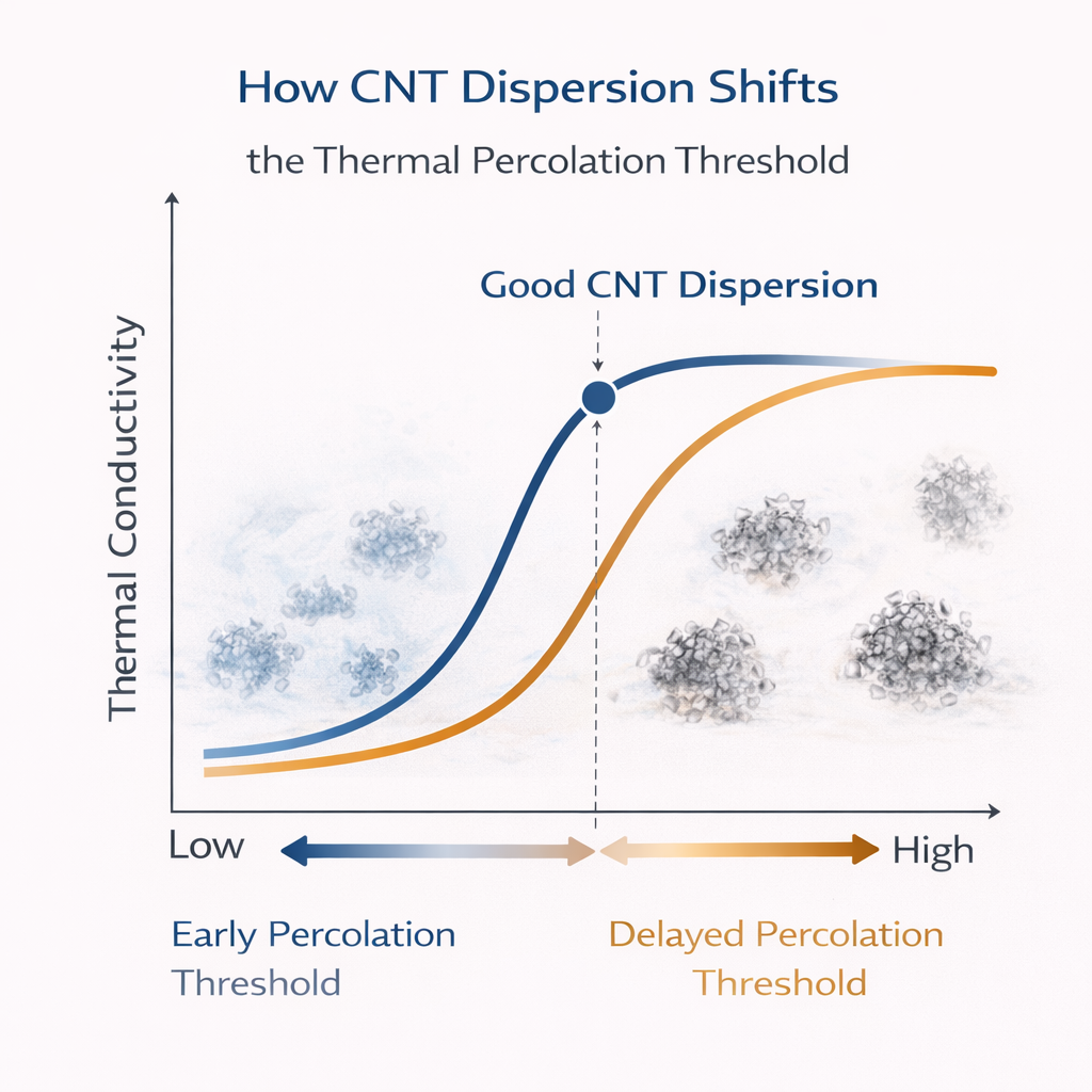
5. How Dispersion Changes the Percolation Curve
Conceptually, dispersion alters the curve in two ways:
-
Threshold Position
-
Good dispersion → early percolation
-
Poor dispersion → delayed or absent percolation
-
-
Slope After Percolation
-
Well-connected networks → sharp conductivity increase
-
Fragmented networks → slow, inefficient gain
-
This explains why some CNT systems show a “sweet spot” early, while others never reach one.
6. Dispersion Mechanisms That Matter Most
6.1 CNT Aspect Ratio Preservation
-
Excessive shear shortens CNTs
-
Reduced aspect ratio raises percolation threshold
Balance is critical:
Enough shear to deagglomerate, not enough to damage CNTs.
6.2 CNT–Matrix Compatibility
Dispersion improves when:
-
Surface energy is matched
-
Functionalization is controlled
-
Resin wets CNT surfaces effectively
Poor compatibility = inevitable re-agglomeration.
6.3 Processing Sequence
CNT dispersion is sensitive to:
-
Order of ingredient addition
-
Mixing temperature
-
Viscosity at mixing stage
Small formulation choices can shift percolation behavior dramatically.
7. Dispersion vs Alignment: A Common Misunderstanding
Alignment can help—but only after dispersion is achieved.
-
Poorly dispersed but aligned CNTs → limited benefit
-
Well-dispersed, randomly oriented CNTs → often outperform aligned clusters
For most industrial systems:
Uniform dispersion beats partial alignment.
8. Hybrid Systems: Dispersion Becomes Easier
In CNT–graphene or CNT–flake hybrids:
-
Graphene sheets help separate CNT bundles
-
CNTs bridge between graphene layers
-
Effective percolation achieved at lower CNT loading
Hybrid networks often:
-
Reduce CNT demand
-
Lower viscosity
-
Improve thermal reliability
9. Engineering Takeaways
-
Thermal percolation is dispersion-driven
-
Good dispersion shifts the threshold to lower CNT loading
-
Poor dispersion wastes CNTs and raises cost
-
Excess shear can be as harmful as insufficient shear
-
Dispersion quality defines the real “sweet spot”
CNT dispersion determines whether CNTs act as:
-
Efficient thermal highways
-
Or expensive inert fillers
Shifting the thermal percolation threshold through dispersion optimization is often the most powerful—and most economical—lever in CNT-based thermal system design.