

TIM vs Gap Filler vs Thermal Pad – An Engineering Comparison
Choosing the right thermal interface material is often more critical than choosing the highest-conductivity filler.
In thermal management design, engineers frequently focus on bulk thermal conductivity (W/m·K) while overlooking the real performance bottleneck:
how heat actually crosses interfaces under real assembly conditions.
Thermal Interface Materials (TIMs), gap fillers, and thermal pads are often grouped together—but from an engineering standpoint, they solve very different problems.
This article provides a practical, application-driven comparison to help you choose the right solution for electronics, batteries, and power systems.
1. The Real Question Is Not “Which Is Better?”
The correct question is:
What interface problem am I actually trying to solve?
Most thermal failures are caused by:
-
Air gaps at interfaces
-
Surface roughness and non-flatness
-
Assembly tolerances
-
Pump-out or aging over thermal cycles
Different materials address different failure modes.
2. What Is a TIM (Thermal Interface Material)?
Typical forms
-
Thermal grease / paste
-
Phase-change materials (PCM)
-
CNT–Graphene hybrid TIMs
-
Liquid or semi-liquid compounds
Primary function
-
Minimize thermal contact resistance (R<sub>tc</sub>)
-
Wet microscopic surface asperities
-
Eliminate trapped air at the interface
Key characteristics
-
Very thin bond line thickness (BLT): typically 10–100 μm
-
High surface conformity
-
Requires controlled assembly pressure
-
Limited gap-filling capability
Where TIMs excel
-
Chip → heat sink
-
Power module → cold plate
-
Battery cell → cooling plate (tight tolerance designs)
Engineering takeaway
TIMs are ideal when surfaces are flat and gaps are minimal—but they are not designed to bridge large gaps.
3. What Is a Gap Filler?
Typical forms
-
Silicone-based dispensable materials
-
CNT- or graphene-enhanced elastomer compounds
-
One- or two-part curable systems
Primary function
-
Fill large and uneven gaps (0.3–5 mm)
-
Maintain thermal contact despite tolerance stack-ups
-
Absorb mechanical stress and vibration
Key characteristics
-
Moderate thermal conductivity
-
High compliance and thickness tolerance
-
Dispensing or curing process required
-
Often doubles as a mechanical buffer
Where gap fillers excel
-
Battery modules and packs
-
Power electronics with uneven heights
-
Assemblies with vibration or thermal expansion mismatch
Engineering takeaway
Gap fillers trade conductivity for robust contact under imperfect geometry.
4. What Is a Thermal Pad?
Typical forms
-
Pre-cured silicone sheets
-
Reinforced elastomer pads
-
Electrically insulating or conductive variants
Primary function
-
Provide repeatable, clean, and fast assembly
-
Combine thermal conduction with electrical insulation
-
Offer predictable thickness and mechanical stability
Key characteristics
-
Fixed thickness (commonly 0.3–3 mm)
-
Lower conformity than grease or gap filler
-
Easy installation and rework
-
Long-term mechanical stability
Where thermal pads excel
-
Consumer electronics
-
Power supplies
-
Applications requiring insulation and fast assembly
Engineering takeaway
Thermal pads prioritize manufacturing consistency and safety over maximum thermal performance.
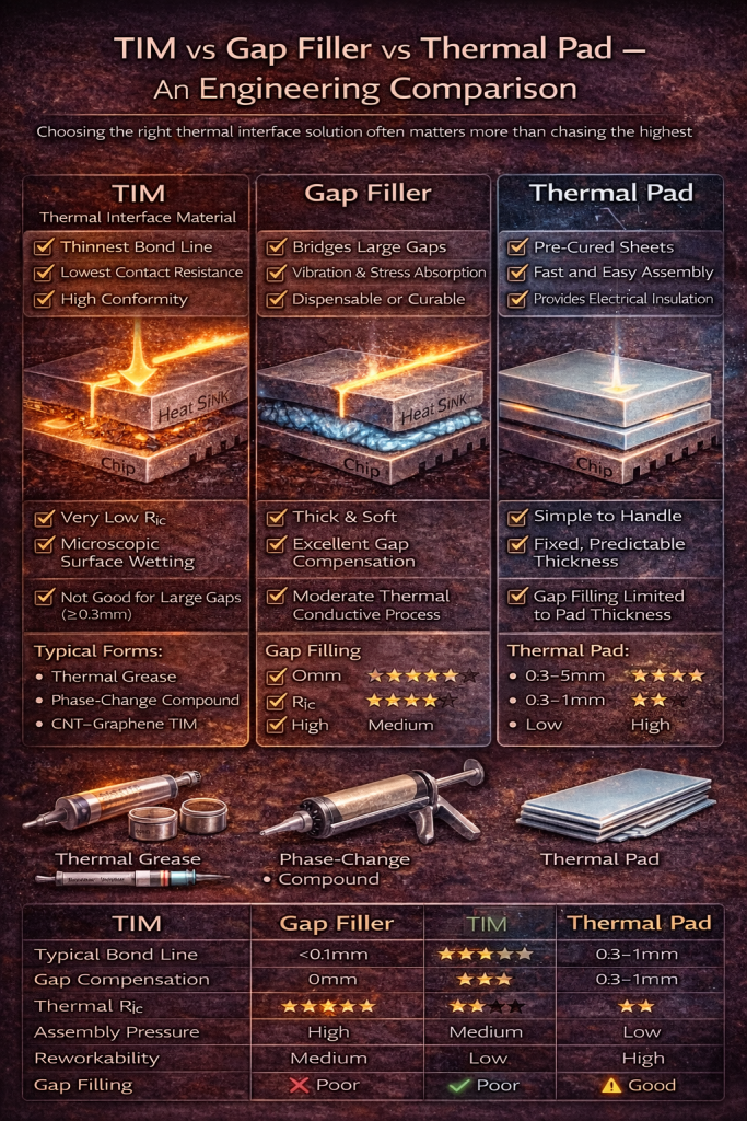
5. Side-by-Side Engineering Comparison
| Parameter | TIM | Gap Filler | Thermal Pad |
|---|---|---|---|
| Typical Thickness | 10–100 μm | 0.3–5 mm | 0.3–3 mm |
| Gap Compensation | ❌ Very limited | ✅ Excellent | ⚠️ Moderate |
| Thermal Contact Resistance | ⭐⭐⭐⭐⭐ | ⭐⭐⭐ | ⭐⭐ |
| Assembly Pressure Needed | Medium–High | Low–Medium | Low |
| Process Complexity | Medium | High | Low |
| Reworkability | Medium | Low | High |
| Long-Term Stability | Depends on formulation | High | Very high |
6. Where CNT–Graphene Materials Change the Equation
Traditional fillers (alumina, BN, silver) rely on particle-to-particle contact, which degrades rapidly under compression loss or aging.
CNT–Graphene hybrid systems introduce:
-
Percolated thermal pathways across interfaces
-
Improved compliance without sacrificing conductivity
-
Reduced pump-out and migration
-
Better performance at lower filler loading
This makes them especially valuable in:
-
Thin TIM layers where contact resistance dominates
-
Gap fillers requiring both softness and conductivity
-
Hybrid pad–TIM designs for power electronics
7. Selection Guide: Which Should You Choose?
Choose a TIM if:
-
Surfaces are flat and well-controlled
-
You need the lowest possible junction temperature
-
Contact resistance dominates the thermal path
Choose a gap filler if:
-
Gap size varies or exceeds 0.3 mm
-
Mechanical stress and vibration matter
-
Assembly tolerance is a challenge
Choose a thermal pad if:
-
Fast, clean assembly is critical
-
Electrical insulation is required
-
Reworkability and consistency matter more than peak performance
8. Final Thought: Interfaces Decide System Reliability
In real systems, the interface—not the bulk material—sets the thermal limit.
Understanding the role of TIMs, gap fillers, and thermal pads allows engineers to:
-
Reduce thermal risk
-
Improve long-term reliability
-
Avoid overdesign and unnecessary cost
The best thermal solution is not the one with the highest datasheet conductivity—but the one that matches the real interface conditions.