
Advanced Carbon Materials in High-Power PCS Systems
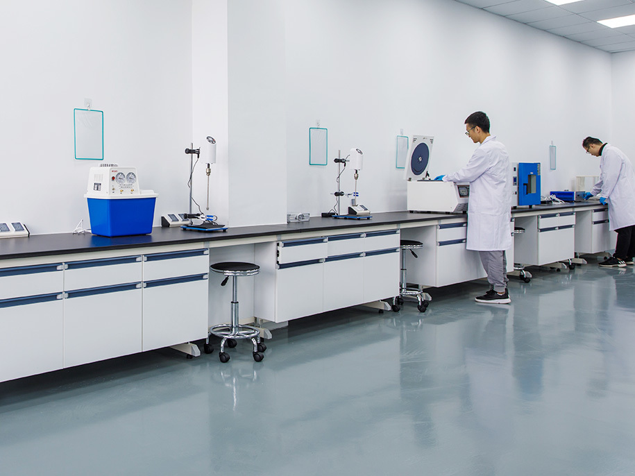
Power Conversion Systems (PCS) are essential components in modern battery energy storage systems. They manage bidirectional power flow between battery systems and the electrical grid, converting direct current (DC) into alternating current (AC) during discharge and converting AC into DC during charging.
As energy storage installations increase in power density, operating duty, and system complexity, PCS manufacturers face growing challenges involving thermal management, electrical insulation, electromagnetic compatibility, mechanical reliability, and long-term operating stability.
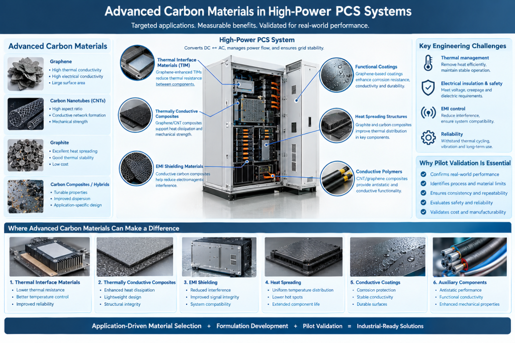
Advanced carbon materials, including graphene, carbon nanotubes (CNTs), graphite, and carbon-based composites, offer several properties that may help address selected engineering challenges. Depending on their structure and formulation, these materials can provide high thermal conductivity, electrical conductivity, lightweight reinforcement, or functional surface properties.
However, their value in PCS systems depends on where and how they are integrated. High electrical conductivity can be beneficial in a conductive interface but undesirable in an insulating thermal-management component. Similarly, high intrinsic thermal conductivity does not automatically translate into lower system-level thermal resistance.
The key opportunity is not to replace conventional PCS components indiscriminately, but to identify specific locations where advanced carbon materials can improve measurable performance without compromising electrical safety, reliability, or manufacturability.
1. Understanding the Engineering Challenges in High-Power PCS Systems
A high-power PCS typically includes power semiconductor modules, DC-link capacitors, busbars, inductors, transformers where applicable, cooling systems, control electronics, protective components, and an enclosure.
Each subsystem has different material requirements.
1.1 Thermal management
Power semiconductor devices generate heat during switching and conduction. Capacitors, magnetic components, busbars, and other electrical components also experience losses.
If heat cannot be removed efficiently, component temperatures may rise, potentially accelerating material degradation, increasing electrical losses, or triggering thermal protection.
Thermal management therefore depends on the complete heat-transfer path, including the semiconductor package, thermal interface material (TIM), cold plate or heat sink, coolant system, and surrounding environment.
1.2 Electrical insulation and safety
High-power PCS equipment contains components operating at potentially hazardous voltages. Electrical insulation, creepage distances, clearance, dielectric strength, and resistance to partial discharge must be addressed through appropriate system design and qualification.
Carbon materials can be electrically conductive, particularly when incorporated into continuous networks. Their use near high-voltage components must therefore be evaluated carefully.
1.3 Electromagnetic interference
High-frequency switching can generate conducted and radiated electromagnetic emissions. These may interfere with control circuits, communication interfaces, sensing equipment, and other electronic systems.
EMI control generally involves enclosure design, grounding, filtering, cable routing, shielding, and circuit layout. Conductive carbon composites may provide supplementary shielding in selected applications, but they are not a substitute for a complete electromagnetic compatibility strategy.
1.4 Reliability under repeated operating cycles
PCS systems may experience frequent changes in power demand, ambient temperature, cooling conditions, and operating modes.
Repeated heating and cooling can stress interfaces, coatings, bonded structures, seals, and composite materials. Material solutions must therefore be assessed under representative thermal and mechanical cycles rather than only under initial laboratory conditions.
2. Graphene for Thermal Interface Materials and Heat Dissipation
Graphene is known for its high intrinsic in-plane thermal conductivity. In engineered products, graphene-based fillers may be incorporated into thermal interface materials, polymer composites, coatings, or other heat-transfer structures.
For PCS manufacturers, the relevant question is whether these formulations can improve heat transfer in a practical assembly.
2.1 Thermal interface materials
Thermal interface materials fill microscopic gaps between contacting surfaces, reducing thermal resistance caused by imperfect contact.
Graphene-enhanced TIM formulations may be investigated for applications between:
- Power semiconductor modules and cold plates.
- Heat-generating electronic components and heat spreaders.
- Selected control-electronics components and thermal enclosures.
The performance of a TIM depends on more than the thermal conductivity of the filler. Important factors include filler orientation, loading, particle contact, binder chemistry, bond-line thickness, surface roughness, compression, and contact resistance.
Graphene’s high in-plane thermal conductivity does not guarantee high through-plane conductivity in a finished TIM. The filler network and its orientation must match the direction of heat flow.
2.2 Thermal interface reliability
Initial thermal resistance is only one performance indicator.
A PCS application may also require the TIM to withstand compression, vibration, temperature cycling, and long operating periods without excessive pump-out, cracking, hardening, or loss of contact.
Validation should therefore include thermal resistance measurements under representative assembly pressure, together with aging and cycling tests where appropriate.
Graphene-based TIMs should be compared against established silicone, ceramic-filled, graphite-based, or other commercially suitable alternatives using consistent test conditions.
3. Graphene and CNTs in Thermally Conductive Polymer Composites
Graphene and CNTs can be incorporated into polymers to create composites with enhanced thermal or electrical functionality.
These composites may be relevant to selected PCS support components, thermal management structures, covers, housings, cable-management parts, and auxiliary electronic assemblies.
However, the intended function determines the appropriate formulation.
3.1 Thermally conductive but electrically insulating materials
Many PCS components require heat dissipation while maintaining electrical isolation.
This presents an important material-selection challenge. Graphene and CNTs are generally conductive, and sufficient filler loading may create an electrically conductive network within a polymer.
A thermally conductive composite intended for use near high-voltage components must therefore meet the required dielectric properties as well as thermal targets.
In some applications, electrically insulating ceramic fillers may be a more appropriate primary solution. Hybrid formulations that combine carbon materials with insulating fillers may be investigated, but their electrical behavior must be demonstrated rather than assumed.
3.2 Thermal and mechanical trade-offs
Increasing filler loading can improve certain thermal pathways, but it may also increase viscosity, reduce processability, alter flexibility, and complicate molding or dispensing.
CNTs may form connected networks at relatively low loading in some formulations because of their high aspect ratio. Graphene platelets can provide extended in-plane heat-transfer pathways, depending on their orientation and dispersion.
Hybrid systems may offer useful combinations of properties, but performance depends on formulation, processing, and the geometry of the finished component.
The optimum design is therefore not necessarily the formulation with the highest carbon content. It is the formulation that meets thermal, electrical, mechanical, and manufacturing requirements simultaneously.
4. Carbon-Based Materials for EMI Shielding
Electromagnetic compatibility is a key consideration in high-power conversion equipment.
Switching devices, high-current conductors, and fast-changing electrical signals can generate electromagnetic disturbances. Shielding materials may help reduce emissions or improve immunity when incorporated into a properly designed enclosure or component.
Graphene, CNTs, conductive carbon composites, and carbon-coated fabrics can be investigated for selected EMI shielding applications.
Potential integration locations include:
- Auxiliary electronics enclosures.
- Shielding covers for control or communication modules.
- Conductive composite panels.
- Flexible shielding layers in selected cable or connector assemblies.
4.1 Shielding performance depends on the complete structure
EMI shielding effectiveness depends on frequency, conductivity, thickness, material continuity, enclosure geometry, seams, grounding, and the source and propagation path of the interference.
A conductive carbon composite may be suitable for one frequency range but insufficient for another. A high shielding value measured on a flat laboratory specimen also does not establish the performance of a complete enclosure with joints, openings, and cable penetrations.
Pilot testing should therefore combine material-level measurements with component-level evaluation where the application warrants it.
4.2 Grounding and electrical continuity
Conductive coatings or composite structures may require reliable electrical connections to the enclosure or grounding system.
Contact resistance, corrosion at interfaces, wear, and changes caused by assembly or environmental exposure can affect performance.
Material selection must be coordinated with the electrical design rather than treated as an independent coating decision.
5. Graphite and Carbon Composites in Heat Spreading
Graphite-based materials are already used in a variety of thermal-management products because of their useful thermal properties and relatively low density.
Depending on the component architecture, flexible graphite sheets or engineered graphite composites may be considered for spreading heat across a surface.
Possible applications in PCS auxiliary electronics include localized heat spreading around control boards, displays, communication modules, or other compact assemblies.
Graphene-based coatings or composites may also be investigated where a thin functional layer is preferred.
However, heat spreading and heat removal are different functions. A material can spread heat effectively without providing a complete route for transferring that heat into a coolant or ambient environment.
A successful design must establish the full thermal path from the heat source to the final heat sink.
Other factors include electrical conductivity, edge isolation, mechanical support, thermal expansion, assembly pressure, and compatibility with adjacent materials.
6. CNTs and Conductive Networks in Selected Auxiliary Components
CNTs are particularly interesting where a conductive network is required at relatively low filler loading, depending on the polymer system and processing conditions.
Potential applications around PCS systems include antistatic components, conductive polymer parts, functional coatings, and selected sensor-related materials.
For example, CNT-modified polymers may be evaluated where static charge accumulation needs to be controlled. Conductive composites may also be investigated for applications requiring a combination of mechanical strength and electrical functionality.
However, the required resistance range must be defined carefully. A material intended for electrostatic dissipation does not necessarily need the low resistance required for a grounding conductor.
For every application, the target electrical property, environmental exposure, mechanical requirements, and applicable safety criteria should be specified before formulation begins.
7. Can Advanced Carbon Materials Improve PCS Energy Efficiency?
Advanced carbon materials may contribute to efficiency improvements indirectly, but the mechanism must be identified and measured.
For example, a thermal interface material that reduces junction-to-coolant thermal resistance may help maintain operating temperatures or provide additional thermal margin. A suitable shielding material may improve integration flexibility. A lightweight composite may reduce the mass of a selected auxiliary structure.
However, none of these improvements automatically guarantees higher electrical conversion efficiency.
PCS conversion losses are primarily influenced by semiconductor characteristics, switching frequency, conduction losses, magnetic components, control strategy, operating point, and system design.
A thermal material may affect efficiency only through specific secondary mechanisms, such as changes in temperature-dependent component losses or cooling-system energy consumption.
A credible evaluation should distinguish between:
- Improved thermal conductivity of a material.
- Reduced thermal resistance of an assembled component.
- Lower component operating temperature.
- Reduced cooling-system energy consumption.
- Improved total PCS conversion efficiency.
These are related but different outcomes. Measurements should be designed to determine which benefit, if any, the material actually provides.
8. Material Selection Must Be Application-Specific
No single carbon material is suitable for every PCS component.
The following comparison provides a starting point for material screening.
| Material | Potential application | Key engineering consideration |
|---|---|---|
| Graphene | Thermal interface materials, functional coatings, polymer composites | Dispersion, orientation, filler loading, interface resistance |
| Carbon nanotubes | Conductive networks, antistatic polymers, selected functional coatings | Network formation, agglomeration, resistance control |
| Graphite | Heat spreaders and thermal-management structures | Directional thermal properties, electrical isolation, mechanical integration |
| Carbon-based hybrid composites | Selected EMI shielding, thermal or multifunctional components | Formulation complexity, repeatability, long-term stability |
This comparison should not be interpreted as a ranking. The most appropriate material depends on the component’s required properties and the constraints of the PCS architecture.
Before selecting a material, engineers should define:
- The specific problem to be solved.
- The target property and measurement method.
- The operating temperature and environmental conditions.
- Electrical insulation or grounding requirements.
- Mechanical and assembly constraints.
- Manufacturing process and expected production volume.
- Cost targets and qualification requirements.
9. Pilot Validation: From Material Potential to PCS Integration
Advanced carbon materials should be validated in stages before being introduced into a high-power PCS.
Stage 1: Define the target component
Identify whether the proposed application concerns thermal management, EMI shielding, antistatic performance, heat spreading, or another specific function.
The component owner and material developer should agree on measurable targets and constraints.
Stage 2: Screen candidate materials
Compare suitable graphene, CNT, graphite, or hybrid formulations against the existing material or component.
Review material specifications, processing requirements, and relevant safety and compatibility information.
Stage 3: Develop and characterize the formulation
For composite materials, investigate dispersion, loading, viscosity, curing or molding conditions, and the relationship between formulation and final properties.
Record the process parameters so that promising results can be reproduced.
Stage 4: Produce representative prototypes
Use representative substrates, dimensions, interfaces, and manufacturing processes. A small laboratory coupon may be useful for screening but may not reproduce the behavior of the final assembly.
Stage 5: Conduct application-specific tests
Depending on the intended use, tests may include:
- Thermal resistance and temperature distribution.
- Dielectric strength and insulation resistance.
- Electrical conductivity or surface resistivity.
- EMI shielding effectiveness.
- Adhesion and mechanical durability.
- Thermal cycling and environmental aging.
- Vibration or other relevant mechanical testing.
The test plan should focus on the actual failure modes and requirements of the target component.
Stage 6: Evaluate repeatability and manufacturing compatibility
Repeat production using multiple batches or representative runs. Examine process stability, variation in key properties, yield, assembly compatibility, and cost.
Stage 7: Validate the integrated component
Where necessary, test the material within the intended component or system. Material-level results cannot replace component-level safety and performance qualification.
Stage 8: Confirm scale-up readiness
Document specifications, processing windows, quality-control procedures, traceability, and acceptance criteria before considering broader production.
For high-power equipment, the validation plan should also align with the manufacturer’s reliability, electrical-safety, and product-qualification requirements.
10. Challenges in Commercializing Carbon Materials for PCS Applications
Several issues can limit the transition from promising material data to commercial adoption.
10.1 Balancing conductivity and insulation
High thermal or electrical conductivity may be beneficial in one location and unacceptable in another. Material requirements must reflect the electrical architecture of the component.
10.2 Maintaining consistent dispersion
Differences in graphene or CNT dispersion can change viscosity, conductivity, thermal performance, and mechanical behavior. Repeatable mixing and quality-control methods are therefore essential.
10.3 Managing interface resistance
The thermal performance of a composite or coating may be limited by interfaces between the material and adjacent components. Surface preparation, bond-line thickness, pressure, and aging can be as important as the intrinsic conductivity of the filler.
10.4 Demonstrating long-term reliability
Initial performance may deteriorate because of thermal cycling, mechanical stress, environmental exposure, or changes in the binder and interface.
Qualification must reflect the expected service conditions.
10.5 Establishing commercial value
Advanced materials may carry higher raw-material or processing costs than established alternatives. Adoption requires a measurable advantage, such as improved thermal margin, reduced component weight, better shielding, or lower maintenance requirements.
A material should be evaluated on its contribution to the complete component or system, not simply on its laboratory properties.
Conclusion
Advanced carbon materials offer potential opportunities in selected high-power PCS applications, particularly thermal interface materials, thermally conductive composites, EMI shielding, heat spreading, and functional conductive components.
Their value depends on the role of each material within the system. Graphene’s thermal properties, CNTs’ ability to form conductive networks, and graphite’s heat-spreading characteristics can be useful, but the final performance is determined by formulation, processing, interfaces, component geometry, and operating conditions.
For PCS manufacturers, the most practical approach is to identify a specific engineering limitation, define measurable performance targets, and validate candidate materials using representative components and operating conditions.
The path to commercialization is application-driven material selection, controlled formulation, pilot validation, and component-level qualification—not the assumption that advanced carbon materials will automatically improve system performance.
Frequently Asked Questions
What are the main applications of graphene in high-power PCS systems?
Potential applications include thermal interface materials, thermally conductive polymer composites, functional coatings, and selected heat-spreading structures. Each application requires validation of thermal, electrical, mechanical, and manufacturing performance.
Can graphene replace conventional thermal interface materials in PCS equipment?
Not automatically. Graphene-enhanced formulations may be evaluated as alternatives or supplements, but their thermal resistance, electrical properties, compression behavior, aging, and assembly compatibility must be demonstrated against the existing solution.
Are CNTs suitable for EMI shielding in PCS systems?
CNT-based composites may provide useful electrical conductivity and EMI shielding in selected applications. Actual effectiveness depends on frequency, thickness, material continuity, enclosure design, grounding, and system-level testing.
Can electrically conductive graphene composites be used near high-voltage components?
Potentially, but only where their electrical properties are compatible with the component’s design and safety requirements. Electrically conductive materials must not compromise required insulation, creepage distances, clearance, or other protective measures.
Does improved thermal conductivity mean higher PCS efficiency?
Not necessarily. Improved material conductivity may reduce thermal resistance, but total PCS efficiency also depends on semiconductor losses, magnetic components, control strategy, operating conditions, and cooling-system consumption. System-level benefits must be measured.
How should a PCS manufacturer evaluate an advanced carbon material?
Start with a clearly defined component-level problem, compare the candidate against an established baseline, conduct representative pilot trials, test relevant safety and performance properties, and verify repeatability and cost before broader adoption.