

Thermal Interface Challenges in Next-Generation Energy Storage: Materials, Reliability, and System-Level Thermal Management
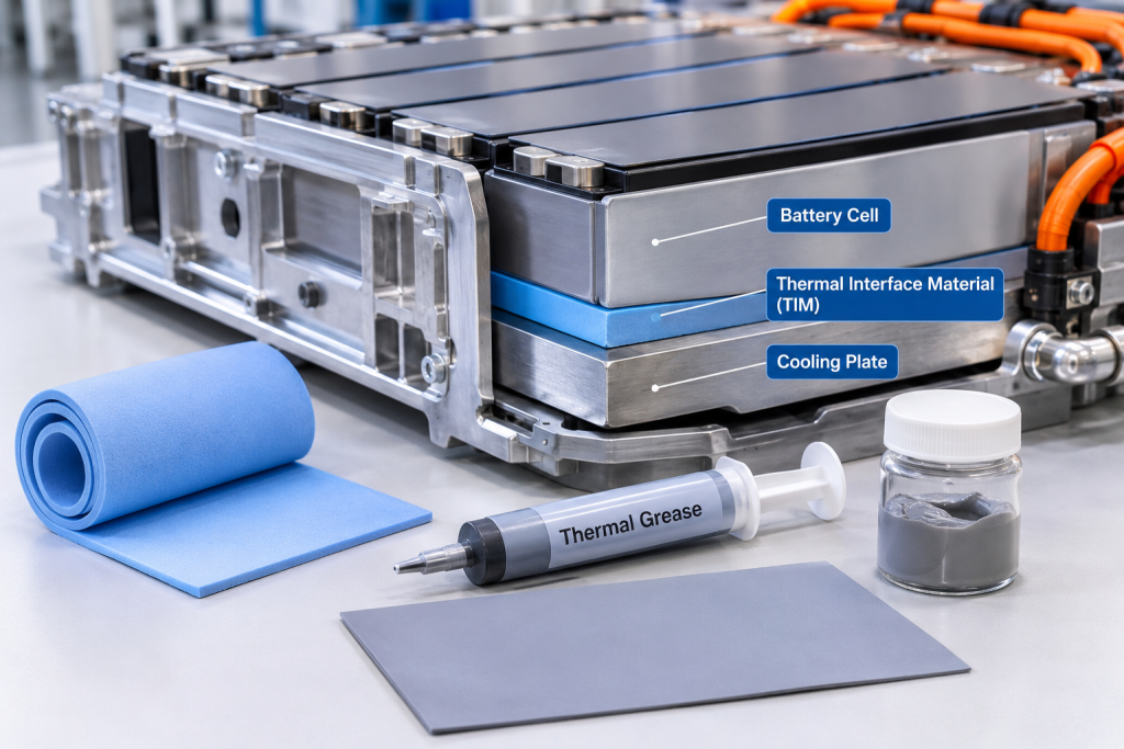
As energy storage systems continue to evolve toward higher energy density, larger capacity, faster charging and discharging, and longer service life, thermal management is becoming an increasingly important engineering challenge.
Battery cells generate heat during charging and discharging due to internal resistance, electrochemical reactions, and other loss mechanisms. If this heat cannot be transferred and dissipated effectively, temperature differences may develop across cells, modules, and battery packs.
These temperature variations can influence battery performance, aging behavior, operational efficiency, and system reliability.
Thermal interface materials (TIMs) play an important role in managing heat transfer between battery cells, module structures, cooling plates, and other thermal management components. However, their performance depends on much more than the intrinsic thermal conductivity of the material.
In practical energy storage applications, thermal interface design must address several interconnected challenges:
- Thermal contact resistance between adjacent components
- Compatibility with different cell and cooling system structures
- Electrical insulation and dielectric safety
- Mechanical compression and dimensional changes
- Material aging under temperature cycling
- Pump-out, migration, and interface degradation
- Manufacturing consistency and installation quality
- Long-term reliability under real operating conditions
This article examines the main thermal interface challenges in next-generation energy storage and explains how material selection, component design, and system-level validation can improve thermal management reliability.
1. Why Thermal Interfaces Matter in Energy Storage Systems
Thermal management in a battery system involves transferring heat from its source to a cooling or heat dissipation structure.
A typical thermal pathway may include:
Battery Cell → Thermal Interface Material → Cooling Plate → Coolant → Heat Exchanger
Depending on the battery architecture, additional interfaces may exist between:
- Adjacent battery cells
- Battery cells and module frames
- Cell surfaces and thermal pads
- Module bases and cooling plates
- Cooling plates and structural supports
- Battery modules and enclosure structures
Each interface introduces potential thermal resistance.
Even when individual components have relatively high thermal conductivity, poor contact between them can significantly reduce overall heat transfer.
1.1 Understanding Thermal Contact Resistance
Thermal contact resistance occurs because two solid surfaces are not perfectly flat at the microscopic level.
Even apparently smooth surfaces contain small irregularities. When two components are placed together, actual contact occurs only at certain microscopic points, while small air gaps remain between other areas.
Because air generally has much lower thermal conductivity than common solid thermal interface materials, these gaps can restrict heat transfer.
A suitable TIM fills surface irregularities and improves thermal contact between components.
The effective thermal resistance of an interface is influenced by:
- Surface roughness and flatness
- Contact pressure
- TIM thickness
- Material thermal conductivity
- Interface wetting and conformity
- Component dimensional tolerances
- Long-term material stability
This explains why a material with a high laboratory thermal conductivity value does not necessarily deliver the best thermal performance in an assembled battery system.
2. The Challenge of Selecting the Right Thermal Interface Material
Different battery architectures require different thermal interface solutions.
The choice depends on the cell format, cooling configuration, mechanical structure, operating temperature, electrical insulation requirements, and manufacturing process.
2.1 Thermal Pads
Thermal pads are commonly used where a compliant, preformed interface is required.
Their advantages include:
- Relatively straightforward installation
- Controlled thickness
- Good conformity to uneven surfaces
- Potential electrical insulation
- Convenient integration into module assembly
However, thermal pads may introduce relatively high thermal resistance if their thickness is excessive.
Their compression characteristics are also important. A pad that is too stiff may not conform adequately to surface irregularities, while one that is too soft may experience excessive deformation or long-term compression changes.
2.2 Thermal Gap Fillers
Liquid or paste-like gap fillers are useful where component tolerances create irregular gaps or where complex geometries make preformed pads difficult to install.
Potential benefits include:
- Good surface conformity
- Ability to fill irregular gaps
- Flexible application thickness
- Adaptability to automated dispensing processes
Their performance depends on viscosity, dispensing accuracy, curing or setting behavior, bond-line thickness, and long-term stability.
Excessive material application can increase the thermal path length and material consumption. Insufficient application may leave air gaps.
2.3 Thermal Greases
Thermal greases can provide low thermal resistance in applications where very thin bond lines are achievable.
However, their suitability depends on mechanical stability and the possibility of material migration.
Potential concerns include:
- Pump-out under repeated thermal expansion and contraction
- Separation of base oil and filler
- Material migration
- Contamination of adjacent components
- Installation and maintenance complexity
For energy storage applications with long service-life expectations, these factors require careful evaluation.
2.4 Phase Change Materials
Phase change materials can soften or change their physical state within a designed temperature range, improving surface conformity and reducing contact resistance.
They may be considered for selected battery thermal management applications.
However, phase change behavior must be evaluated alongside:
- Transition temperature
- Latent heat capacity
- Thermal conductivity
- Material containment
- Leakage or migration risks
- Repeated thermal cycling stability
Phase change materials are not automatically suitable for every battery interface. Their operating temperature range and mechanical integration must match the actual system requirements.
3. Balancing Thermal Conductivity and Electrical Insulation
One of the most important material selection challenges in battery thermal management is balancing heat transfer with electrical safety.
Battery modules contain conductive components, electrical connections, and potentially exposed metal surfaces. Thermal interface materials may need to provide both effective heat transfer and reliable electrical insulation.
These two requirements are not always easy to achieve simultaneously.
3.1 Electrically Insulating Thermal Materials
Common electrically insulating thermal fillers include:
- Aluminum oxide (Al₂O₃)
- Aluminum nitride (AlN)
- Hexagonal boron nitride (h-BN)
- Other ceramic-based functional fillers
These materials can be incorporated into polymer matrices to improve thermal conductivity while maintaining electrical insulation, subject to formulation and testing.
Their performance depends on filler concentration, particle size, morphology, orientation, and dispersion.
3.2 Electrically Conductive Thermal Fillers
Other materials, including graphite, graphene, carbon nanotubes, and metallic fillers, can provide useful thermal transport characteristics.
However, many carbon-based and metallic fillers are electrically conductive.
This creates additional design requirements when the TIM is positioned near electrical conductors or exposed cell terminals.
Potential approaches include:
- Using electrically insulating ceramic filler systems
- Designing multilayer thermal interface structures
- Applying electrically insulating coatings where appropriate
- Separating electrical insulation and thermal conduction functions
- Controlling material placement and edge coverage
The key principle is that thermal conductivity and electrical insulation must be treated as separate performance requirements.
A material should not be selected based on thermal conductivity alone when dielectric safety is also critical.
4. Mechanical Compression and Interface Stability
Thermal interface performance is strongly affected by mechanical conditions.
In a battery module, the interface between cells and cooling structures may experience compression from assembly forces, module frames, fastening systems, and thermal expansion.
The selected TIM must maintain effective contact under these conditions.
4.1 Compression and Contact Pressure
Thermal pads and gap fillers require appropriate contact conditions to reduce interfacial resistance.
Insufficient compression may leave air gaps and increase thermal resistance.
Excessive compression may cause:
- Unwanted deformation
- Material extrusion
- Excessive mechanical stress on components
- Changes in cell or module dimensions
- Damage to sensitive interfaces
The optimal compression range depends on the material’s mechanical properties and the battery module design.
4.2 Compression Set
Compression set describes the permanent deformation that remains after a material has been compressed and subsequently released.
A TIM with excessive compression set may lose some of its ability to maintain contact pressure over time.
This can gradually increase interface resistance.
For long-life energy storage systems, compression set should be evaluated under relevant temperature and loading conditions.
4.3 Battery Cell Expansion
Some battery chemistries and cell designs experience dimensional changes during operation and aging.
For example, electrode expansion and contraction during cycling can contribute to changes in overall cell thickness.
The thermal interface material must accommodate these changes without losing contact or imposing excessive mechanical stress.
This is particularly important for large-format prismatic and pouch cells, where module-level dimensional variation can influence interface uniformity.
5. Thermal Cycling, Aging, and Long-Term Reliability
Energy storage systems operate through repeated charging and discharging cycles, often under changing ambient conditions.
These conditions create thermal cycling across cells, module structures, cooling plates, and interface materials.
Over time, repeated expansion and contraction can affect TIM performance.
5.1 Pump-Out and Material Migration
Pump-out occurs when repeated mechanical and thermal movement causes a thermal interface material to move away from its original contact area.
This may reduce the effective interface coverage and increase thermal resistance.
The risk depends on:
- Material viscosity and rheology
- Filler loading
- Bond-line thickness
- Surface geometry
- Contact pressure
- Temperature variation
- Mechanical movement
Materials with better structural stability may be preferred where repeated cycling and vibration are expected.
5.2 Aging and Chemical Stability
Polymer-based thermal interface materials may experience changes in their physical or chemical properties during prolonged exposure to elevated temperatures.
Potential aging mechanisms include:
- Polymer oxidation
- Hardening or softening
- Filler-matrix separation
- Loss of adhesion
- Volatile component loss
- Moisture-related degradation
The actual failure mechanisms depend on the material formulation and operating environment.
5.3 Thermal Resistance Drift
Initial thermal performance does not necessarily represent long-term performance.
A TIM may show good thermal resistance immediately after installation but degrade after repeated thermal cycling, compression, or environmental exposure.
Therefore, long-term testing should measure changes in thermal resistance rather than only recording initial conductivity.
6. Thermal Interface Challenges in Different Battery Architectures
Different battery formats and cooling structures create different interface requirements.
6.1 Prismatic Battery Systems
Prismatic cells are often arranged in tightly packed module structures.
Thermal interfaces may be installed between cell surfaces and cooling plates, or between cells and dedicated heat transfer structures.
Key challenges include:
- Large contact areas
- Cell thickness variation
- Module compression
- Surface flatness
- Uniform thermal contact
- Assembly tolerance management
A TIM must provide consistent contact without creating excessive mechanical stress.
6.2 Pouch Cell Systems
Pouch cells are flexible and may experience dimensional changes during operation.
Thermal interface design must account for:
- Cell swelling
- Mechanical restraint
- Surface conformity
- Compression distribution
- Edge sealing and protection
- Consistent contact with cooling structures
Compliant thermal pads or appropriately designed gap fillers may be considered depending on the module architecture.
6.3 Cylindrical Battery Systems
Cylindrical cells introduce geometric challenges because their curved surfaces do not naturally provide large flat contact areas.
Thermal management designs may use:
- Thermally conductive adhesives
- Gap fillers
- Thermally conductive structural materials
- Cooling channels or plates
- Specially designed cell holders
The interface geometry and material placement must be optimized to achieve effective heat transfer without creating unnecessary assembly complexity.
7. Integration with Liquid Cooling Systems
Liquid cooling is increasingly important in high-capacity energy storage systems because it can provide controlled heat removal through cooling plates and channels.
However, liquid cooling does not eliminate thermal interface challenges.
The thermal pathway between the battery cell and cooling plate remains important.
A typical configuration includes:
Battery Cell → TIM → Cooling Plate → Coolant Channel
The overall performance depends on the combined thermal resistance of these components.
7.1 Cooling Plate Contact
A cooling plate may have excellent internal heat transfer characteristics, but poor contact between the cell and plate can restrict heat flow.
The TIM must accommodate surface irregularities while maintaining an appropriate bond-line thickness.
7.2 Material Compatibility
The thermal interface material should be compatible with nearby materials, including:
- Aluminum cooling plates
- Metal housings
- Polymer insulation components
- Adhesives and sealants
- Coatings and surface treatments
Potential concerns include corrosion-related interactions, chemical incompatibility, contamination, and degradation of adjacent materials.
7.3 Leakage and Contamination Considerations
In liquid-cooled systems, coolant leakage can affect nearby materials and electrical components.
TIM selection should consider the possibility of exposure to the relevant coolant chemistry and operating environment.
This does not mean every TIM must directly contact coolant. Rather, the system design should establish whether accidental exposure is credible and whether the selected material can tolerate the expected conditions.
8. Manufacturing and Installation Challenges
Even a well-designed thermal interface material can perform inconsistently if its installation process is not controlled.
Manufacturing variables can have a direct effect on thermal resistance.
8.1 Bond-Line Thickness Control
The bond-line thickness is the final thickness of the thermal interface material between two surfaces.
An excessively thick layer increases the distance heat must travel through the TIM.
For a simplified one-dimensional material layer:
[
R_{\mathrm{TIM}}=\frac{t}{kA}
]
Where:
- (R_{\mathrm{TIM}}) is the thermal resistance of the material layer
- (t) is the bond-line thickness
- (k) is the thermal conductivity
- (A) is the effective contact area
This simplified equation does not include additional contact resistance at the material interfaces.
It illustrates why reducing bond-line thickness can improve thermal performance, provided adequate coverage and mechanical reliability are maintained.
8.2 Dispensing and Application Consistency
For liquid gap fillers and thermal adhesives, application consistency is essential.
Important process parameters include:
- Dispensing volume
- Material temperature
- Mixing ratio for two-component systems
- Application speed
- Surface cleanliness
- Curing conditions
- Dispensing path and coverage
Incomplete coverage may create local thermal bottlenecks.
Excessive dispensing may increase material consumption and interfere with component assembly.
8.3 Surface Preparation
Dust, oil, moisture, and other contaminants can reduce adhesion or interfere with thermal contact.
Surface preparation procedures should be compatible with the battery components and selected TIM chemistry.
8.4 Automated Manufacturing
As battery production becomes more automated, TIM application processes must support repeatable dispensing, inspection, and quality control.
Material viscosity, curing time, storage conditions, and packaging stability can all influence production efficiency.
9. Testing and Validation of Thermal Interface Materials
A comprehensive validation program should evaluate both material-level properties and assembled system performance.
9.1 Material-Level Testing
| Test | Purpose |
|---|---|
| Thermal conductivity | Measure intrinsic heat transfer capability |
| Thermal impedance or resistance | Evaluate heat transfer through the interface |
| Dielectric strength | Assess electrical insulation capability |
| Volume resistivity | Evaluate electrical insulation properties |
| Hardness | Characterize material stiffness |
| Compression stress | Understand force required for deformation |
| Compression set | Evaluate permanent deformation |
| Adhesion | Assess bonding to relevant surfaces |
| Rheological testing | Evaluate dispensing and flow behavior |
| Thermal aging | Examine long-term material stability |
Thermal conductivity testing and thermal interface resistance testing should not be treated as interchangeable.
A material may have high bulk conductivity but still exhibit poor assembled interface performance because of excessive thickness, poor contact, or unsuitable mechanical properties.
9.2 Environmental and Reliability Testing
For energy storage applications, additional tests may include:
- Thermal cycling
- High-temperature storage
- Humidity exposure
- Vibration testing
- Mechanical compression cycling
- Chemical compatibility testing
- Coolant exposure testing where relevant
- Long-term interface resistance monitoring
Test conditions should reflect the intended application and operating environment.
9.3 System-Level Thermal Validation
Material-level tests cannot fully predict the thermal behavior of a battery module.
System-level validation should examine:
- Cell surface temperature distribution
- Temperature difference between cells
- Heat transfer to cooling plates
- Thermal response during charging and discharging
- Performance under different ambient temperatures
- Behavior under representative operating loads
- Long-term thermal consistency
The objective is to verify that the complete interface structure performs as intended within the battery system.
10. How Advanced Carbon Materials May Contribute to Thermal Interface Development
Advanced carbon materials, including graphene, graphite, and carbon nanotubes, are attracting interest in thermal management applications.
Their potential lies in their thermal transport characteristics and ability to be incorporated into polymer-based composite systems.
However, their use in battery thermal interfaces requires careful consideration.
10.1 Graphene and Graphite
Graphene and graphite can provide high thermal conductivity, particularly along preferred directions.
They may be considered in:
- Thermally conductive polymer composites
- Thermal spreading films
- Flexible heat transfer layers
- Hybrid thermal interface formulations
However, their electrical conductivity may create insulation challenges.
Filler orientation is also important because in-plane and through-plane thermal conductivity can differ significantly.
A material with excellent in-plane thermal conductivity may not deliver equivalent performance through its thickness.
10.2 Carbon Nanotubes
CNTs can form interconnected structures within polymer matrices.
Their high aspect ratio may contribute to thermal transport pathways, although performance depends on dispersion, loading, filler-matrix interactions, and network structure.
Potential formulation challenges include:
- CNT agglomeration
- Increased viscosity
- Dispersion stability
- Electrical conductivity
- Manufacturing cost
- Reproducibility
10.3 Hybrid Filler Systems
Hybrid formulations may combine different fillers to balance thermal conductivity, electrical insulation, rheology, and mechanical properties.
For example, electrically insulating ceramic fillers may be combined with other functional materials to modify thermal transport and processing behavior.
However, adding graphene or CNTs to an insulating formulation can change its electrical properties.
Therefore, hybrid filler development must evaluate thermal and dielectric performance together.
The most appropriate material is not necessarily the one with the highest thermal conductivity. It is the one that satisfies the complete set of system requirements.
11. Future Trends in Thermal Interface Materials for Energy Storage
As energy storage technologies develop, thermal interface materials are likely to become more application-specific.
Several trends are worth monitoring.
11.1 Higher Thermal Performance at Lower Thickness
Battery manufacturers are looking for materials that can reduce thermal resistance without requiring excessive interface thickness.
This requires improvements in filler networks, surface conformity, and mechanical design.
11.2 Electrically Insulating High-Thermal-Conductivity Composites
There is growing interest in ceramic-filled polymer systems that combine effective heat transfer with electrical insulation.
This is particularly relevant to battery modules where thermal and dielectric requirements must be satisfied simultaneously.
11.3 Flexible and Compressible Interface Materials
As battery formats and module structures evolve, compliant materials that accommodate dimensional changes may become increasingly important.
11.4 Longer-Term Reliability
Energy storage systems are designed for extended operation.
TIM development will therefore place greater emphasis on compression stability, thermal cycling performance, aging resistance, and long-term interface integrity.
11.5 Application-Specific Material Formulation
Instead of developing one universal thermal interface material, suppliers may increasingly develop different formulations for prismatic, pouch, and cylindrical cell systems.
Material selection will depend on the complete thermal pathway, mechanical structure, manufacturing process, and operating environment.
12. From Material Selection to System-Level Validation
Successful thermal interface development requires coordination between material suppliers, battery manufacturers, cooling system designers, and testing organizations.
A practical development process can be divided into several stages.
Stage 1: Define Application Requirements
Identify the battery format, thermal management architecture, operating temperature range, target thermal resistance, electrical insulation requirements, and mechanical constraints.
Stage 2: Screen Candidate Materials
Compare thermal pads, gap fillers, greases, adhesives, and composite materials based on the actual interface requirements.
Stage 3: Conduct Material Characterization
Evaluate thermal conductivity, interface resistance, dielectric properties, compression behavior, and environmental stability.
Stage 4: Develop Interface Prototypes
Prepare representative material samples and test them with relevant cell surfaces, cooling plates, and structural components.
Stage 5: Perform System-Level Testing
Evaluate temperature distribution, heat transfer, mechanical integrity, and reliability under representative operating conditions.
Stage 6: Pilot Manufacturing Validation
Assess dispensing consistency, assembly compatibility, material consumption, production efficiency, and batch repeatability.
Stage 7: Long-Term Reliability Assessment
Monitor thermal resistance and mechanical performance after relevant thermal, mechanical, and environmental aging tests.
This process helps distinguish between a material that performs well in laboratory testing and one that can be reliably integrated into an industrial battery system.
Conclusion
Thermal interface challenges in next-generation energy storage are not limited to achieving higher thermal conductivity.
Effective thermal management requires a complete understanding of contact resistance, interface geometry, electrical insulation, compression behavior, material aging, manufacturing consistency, and system-level thermal performance.
Thermal pads, gap fillers, greases, adhesives, and advanced composite materials each offer different advantages and limitations. Their suitability depends on battery architecture, cooling design, mechanical requirements, and long-term operating conditions.
Graphene, graphite, CNTs, and ceramic-based fillers may offer opportunities for developing advanced thermal interface composites. However, their practical value must be demonstrated through application-specific formulation, dielectric testing, mechanical evaluation, and pilot-scale validation.
Ultimately, the next generation of energy storage systems will require thermal interface solutions designed not simply around material properties, but around the performance and reliability of the complete battery system.
Questions
1. What is a thermal interface material in battery systems?
A thermal interface material is used between two components to improve heat transfer by filling microscopic gaps and reducing thermal contact resistance. Common examples include thermal pads, gap fillers, thermal greases, and thermally conductive adhesives.
2. Why is thermal contact resistance important in energy storage?
Thermal contact resistance can restrict heat transfer between battery cells and cooling structures. Even if the cooling plate has excellent heat dissipation capability, a poor interface can reduce the effectiveness of the complete thermal management system.
3. What is the difference between thermal conductivity and thermal interface resistance?
Thermal conductivity describes the ability of a material to conduct heat. Thermal interface resistance reflects the resistance to heat transfer across an assembled interface, including the effects of material thickness and contact conditions.
4. Why must battery thermal interface materials provide electrical insulation?
Battery modules contain electrical conductors and potentially exposed conductive surfaces. A thermally conductive but electrically conductive material may create electrical risks if it bridges components that must remain isolated.
5. Can graphene improve thermal interface materials?
Graphene may improve thermal transport in polymer composites, particularly when its dispersion and orientation are properly controlled. However, its electrical conductivity, viscosity effects, and processing requirements must also be considered.
6. Are CNTs suitable for thermal interface applications?
CNTs can contribute to thermal transport networks in composite materials. Their effectiveness depends on dispersion, concentration, filler interactions, and the required electrical properties of the final material.
7. How can long-term TIM reliability be evaluated?
Relevant tests include thermal cycling, compression set, high-temperature aging, vibration, chemical compatibility, and thermal resistance monitoring. System-level testing is also important because material performance can change after assembly.
8. What is the most important factor when selecting a TIM for battery cooling?
There is no single universal factor. Selection should consider thermal resistance, electrical insulation, mechanical compliance, interface thickness, aging behavior, manufacturing compatibility, and the requirements of the specific battery architecture.