
Graphene Glass Heating vs. Conventional Infrared Heating: Performance and Design Considerations
Electric heating technologies are widely used in industrial equipment, household appliances, semiconductor processing, surface treatment, and precision temperature-control systems. As applications demand faster response, improved temperature uniformity, compact structures, and higher operating temperatures, manufacturers are exploring alternative heating materials and architectures.
Graphene glass heating is one emerging approach. It typically integrates a graphene-based conductive heating layer with a glass or glass-ceramic substrate, creating a planar electrical heating structure. When current passes through the conductive layer, electrical energy is converted into heat, which is transferred through the glass and released to the surrounding environment through conduction, convection, and thermal radiation.
Conventional infrared heating systems use different emitter technologies, including quartz tubes, ceramic elements, metallic resistance heaters, and other electrically heated structures. Their performance depends on emitter material, operating temperature, surface emissivity, wavelength characteristics, reflector design, and installation geometry.
Both approaches can provide useful heating performance, but they are not interchangeable in every application.
The choice between graphene glass heating and conventional infrared heating should be based on the required temperature range, heating uniformity, response time, thermal output, lifetime, safety, and system-level design.
This article compares the two approaches and explains the engineering considerations involved in developing reliable graphene glass heating systems.
1. Understanding the Two Heating Technologies
1.1 How graphene glass heating works
A graphene glass heater generally consists of several functional layers:
- Glass or glass-ceramic substrate.
- Graphene-based conductive heating layer.
- Electrical electrodes or busbars.
- Insulating or protective layers where required.
- Mechanical support and electrical connection structures.
When voltage is applied, current flows through the conductive graphene-based layer. Its electrical resistance generates heat according to Joule’s law:
[
P=I^2R=\frac{V^2}{R}
]
Where:
- (P) is electrical power.
- (I) is current.
- (V) is applied voltage.
- (R) is electrical resistance.
The generated heat is transferred into the glass substrate and then distributed across the heating surface.
Depending on the surface temperature and emissivity, the heated glass also emits thermal radiation, including infrared radiation.
The final heating behavior depends on the electrical properties of the conductive layer, electrode configuration, substrate thickness, thermal conductivity, surface emissivity, and heat-loss conditions.
1.2 How conventional infrared heating works
Conventional infrared heaters use an electrically heated emitter to produce thermal radiation.
Common technologies include:
Quartz infrared heaters
These typically use a resistance wire or filament inside a quartz tube. The heated element emits infrared radiation, and the quartz envelope influences the transmission and spectral characteristics of the emitted energy.
Ceramic infrared heaters
Ceramic elements are electrically heated and emit thermal radiation from their surfaces. They are often used in industrial heating applications requiring relatively robust emitter structures.
Metal-sheathed resistance heaters
These use a resistance element inside a protective metal structure. Heat is transferred through the sheath and then released through conduction, convection, and radiation.
These technologies have different temperature ranges, response characteristics, spectral distributions, mechanical properties, and installation requirements.
Therefore, graphene glass heating should be compared with a clearly defined conventional heater rather than treating all infrared heaters as one uniform technology.
2. Key Differences in Heating Structure
The most visible difference is the physical architecture.
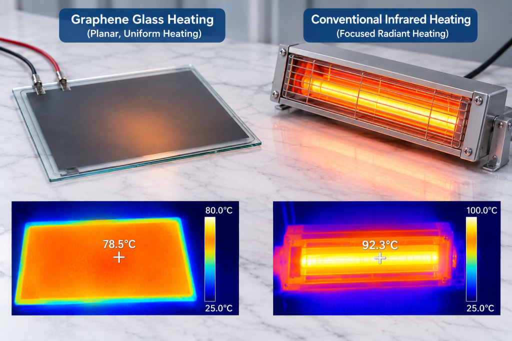
A graphene glass heater can provide a relatively flat heating surface, with the conductive layer distributed across a glass substrate.
Conventional infrared heaters often use tubular, panel, or ceramic emitter structures.
| Design factor | Graphene glass heating | Conventional infrared heating |
|---|---|---|
| Heating structure | Conductive layer integrated with glass or glass-ceramic | Quartz tube, ceramic emitter, or other resistance-heating structure |
| Heating geometry | Typically planar | Tubular, panel, or other geometries |
| Heat generation | Joule heating in a conductive film | Joule heating in a resistance element or conductive body |
| Heat transfer | Conduction through glass, convection, and radiation | Radiation, convection, and conduction depending on structure |
| Temperature uniformity | Depends on film resistance, electrodes, and substrate design | Depends on emitter geometry, element distribution, and reflector design |
| Response time | Depends on substrate thermal mass and power density | Depends on emitter mass, construction, and operating temperature |
| Design flexibility | Potential for integrated planar structures | Established range of tubular, ceramic, and industrial emitter designs |
| Main engineering challenge | Film stability, electrode interfaces, glass compatibility, and encapsulation | Element durability, thermal stress, emitter aging, and installation conditions |
The table provides a general comparison. Actual performance must be established using products with comparable dimensions, power input, operating conditions, and measurement methods.
3. Heating Efficiency: What Should Actually Be Compared?
Heating efficiency is often used to compare different electric heating technologies, but the term can describe several different measurements.
For a meaningful comparison, engineers should distinguish between electrical-to-heat conversion and useful heat delivered to the target.
3.1 Electrical-to-thermal conversion
Both graphene glass heaters and conventional electric resistance heaters convert electrical energy into heat.
The fundamental conversion mechanism is Joule heating. Neither technology automatically has an inherent advantage simply because of its heating material.
The practical difference lies in how heat is generated, distributed, transferred, and lost.
3.2 Radiation efficiency
The radiative heat output of a surface can be described by the Stefan-Boltzmann relationship:
[
P_{\mathrm{rad}}=\varepsilon\sigma A(T_s^4-T_a^4)
]
Where:
- (\varepsilon) is the effective surface emissivity.
- (\sigma) is the Stefan-Boltzmann constant.
- (A) is the emitting surface area.
- (T_s) is the absolute surface temperature.
- (T_a) is the surrounding absolute temperature.
This relationship shows why surface temperature and emissivity matter when comparing infrared heating performance.
A graphene-based conductive film does not automatically guarantee higher infrared output. The radiation characteristics depend on the complete emitting surface, including the glass substrate, coatings, protective layers, and operating temperature.
3.3 Useful heat delivered to the target
In many applications, the most important metric is not total heat generated but how effectively the system heats the intended object.
For example:
- A planar heater may distribute heat over a large contact surface.
- A quartz infrared emitter may provide more concentrated radiant heating.
- A ceramic heater may be suitable for maintaining a stable temperature over a defined area.
- A reflector-based infrared system may direct a larger proportion of its radiation toward the target.
A fair comparison should measure the temperature and energy absorbed by the target under equivalent operating conditions.
Useful indicators include:
- Time required to reach the target temperature.
- Temperature distribution across the target.
- Electrical energy consumed during a heating cycle.
- Heat losses to the surroundings.
- Temperature stability during continuous operation.
4. Temperature Uniformity and Heating Response
Temperature uniformity is an important design consideration in glass heating systems, laboratory equipment, industrial processing, and precision heating applications.
4.1 Planar heating with graphene glass
A graphene-based heating layer can be designed to distribute electrical resistance across a planar surface.
In principle, this provides an opportunity to create a relatively uniform heating area without relying on a separate tubular emitter.
However, uniform temperature does not result automatically from using graphene.
It depends on:
- Uniformity of the conductive film.
- Sheet resistance distribution.
- Electrode geometry and contact resistance.
- Substrate thickness and thermal conductivity.
- Heat loss at edges and mounting points.
- Applied voltage and power density.
- Temperature-dependent changes in electrical resistance.
Local differences in film resistance can create uneven current distribution and localized heating.
Electrode design is particularly important. Poorly designed busbars or electrical contacts may cause current crowding near connection points and generate local hot spots.
4.2 Conventional infrared heating distribution
Conventional infrared systems may use multiple emitters, reflectors, spacing adjustments, and controlled heating zones to achieve the required temperature distribution.
For large industrial surfaces, emitter arrangement and target distance can strongly influence uniformity.
For example, a quartz tube heater may produce a different spatial heating profile from a ceramic panel heater. Reflectors and controlled emitter placement can help improve the distribution.
4.3 How to evaluate uniformity
A meaningful temperature-uniformity evaluation should include:
- Maximum and minimum surface temperature.
- Average temperature across the heating area.
- Temperature deviation or standard deviation.
- Local hot-spot identification.
- Temperature distribution during warm-up.
- Temperature stability after reaching equilibrium.
Infrared cameras can help identify surface-temperature variations, but emissivity settings and surface reflections must be controlled to avoid misleading measurements.
For development projects, measurements should be repeated at different power levels and under representative ambient and mounting conditions.
5. Maximum Operating Temperature and Long-Term Stability
Operating temperature is one of the most important differences between heating technologies.
Conventional infrared heating systems cover a wide range of operating temperatures depending on the emitter type and construction.
Graphene glass heating systems also have potential for different temperature ranges, but the maximum practical temperature is determined by the complete device architecture.
5.1 The graphene heating layer
The conductive layer must maintain suitable electrical resistance and structural integrity during repeated heating cycles.
Potential degradation mechanisms include:
- Changes in electrical resistance.
- Oxidation or chemical degradation.
- Cracking or delamination.
- Changes in the conductive network.
- Degradation of protective coatings.
- Deterioration at the electrode interface.
The stability of the graphene layer depends on its composition, processing, deposition method, atmosphere, encapsulation, and operating conditions.
The performance of graphene powder or a laboratory coating sample cannot independently establish the service life of a complete heating element.
5.2 Glass and glass-ceramic substrate limitations
The substrate must tolerate repeated temperature changes without excessive deformation, cracking, or loss of mechanical integrity.
Important parameters include:
- Maximum continuous-use temperature.
- Thermal expansion coefficient.
- Thermal conductivity.
- Thermal shock resistance.
- Mechanical strength.
- Chemical compatibility with the heating layer.
- Compatibility with electrodes and sealing materials.
Glass and glass-ceramic materials can behave very differently. A substrate selected for moderate-temperature heating may not be appropriate for a high-temperature application.
5.3 Conventional infrared emitter durability
Conventional infrared systems also have temperature-dependent limitations.
Quartz heaters may experience changes in the resistance element, envelope, or electrical connections. Ceramic heaters may be affected by thermal cycling, mechanical stress, and material aging.
The actual service life depends on operating temperature, power cycling, atmosphere, mounting, and manufacturing quality.
A fair comparison should use continuous-operation tests and repeated thermal cycling under defined conditions.
6. Electrical Design and Safety Considerations
Electrical design is critical for both technologies, especially in high-power heating applications.
6.1 Resistance and power matching
The heater’s electrical resistance must be matched to the supply voltage and required power.
For a resistive heater:
[
R=\frac{V^2}{P}
]
For example, a heater designed for 220 V operation requires an appropriate resistance based on the target power output.
However, resistance should not be evaluated only at room temperature. The electrical behavior of the heating layer may change with temperature.
The design should account for:
- Cold resistance.
- Operating resistance.
- Temperature coefficient of resistance.
- Current density.
- Power density.
- Electrode contact resistance.
- Electrical insulation requirements.
6.2 Electrode and connection design
Electrodes connect the conductive heating layer to the external power supply.
The interface must maintain reliable electrical contact while tolerating temperature changes and mechanical stress.
Poor connections may lead to:
- Localized overheating.
- Increased contact resistance.
- Oxidation.
- Delamination.
- Electrical failure.
Electrode materials, joining methods, interface geometry, and protective structures should be evaluated as part of the complete heater design.
6.3 Insulation and protection
A graphene-based conductive layer may require electrical isolation from the external environment and surrounding components.
Depending on the product architecture, protection may involve glass layers, insulating coatings, edge sealing, encapsulation, or other insulation structures.
The complete heater must be tested for dielectric strength, insulation resistance, leakage current, and other relevant electrical-safety requirements.
High operating temperature also places additional demands on insulation and sealing materials.
7. Encapsulation and Packaging: A Critical Design Factor
The performance of a graphene glass heating element depends not only on the heating layer but also on how the complete structure is packaged.
Encapsulation can protect the conductive layer from environmental exposure, mechanical damage, and chemical contamination.
However, the protective structure must not introduce unacceptable thermal resistance or mechanical stress.
7.1 Protective-layer selection
Possible protective materials include glass, glass-ceramic, ceramic coatings, and other temperature-resistant materials.
Selection depends on:
- Operating temperature.
- Thermal expansion compatibility.
- Optical and infrared transmission requirements.
- Electrical insulation.
- Adhesion.
- Chemical stability.
- Mechanical durability.
A protective layer that performs well at moderate temperatures may degrade or lose adhesion at higher operating temperatures.
7.2 Thermal expansion mismatch
Different materials expand at different rates when heated.
The graphene-based film, glass substrate, electrodes, and protective layers must be sufficiently compatible to avoid excessive internal stress.
Repeated thermal cycling can gradually create cracks, delamination, or changes in electrical contact.
This makes thermal-expansion matching and interface engineering essential during product development.
7.3 Environmental protection
Depending on the application, the heater may need protection against humidity, dust, oxidation, chemicals, or mechanical contact.
The encapsulation design should be based on the actual operating environment rather than assuming that glass alone provides complete protection.
8. Application Scenarios: Where Each Technology May Be Suitable
Neither graphene glass heating nor conventional infrared heating is universally superior. Their suitability depends on the heating task.
8.1 Planar surface heating
Graphene glass heating may be considered for applications requiring a flat, integrated heating surface.
Potential applications include:
- Heated glass panels.
- Laboratory heating surfaces.
- Industrial flat-surface heaters.
- Compact heating modules.
- Selected appliance heating structures.
The key requirements are surface uniformity, mechanical strength, electrical insulation, and reliable thermal cycling.
8.2 Industrial radiant heating
Conventional infrared heaters are widely used where direct radiant heating is required.
Applications include:
- Paint and coating curing.
- Plastic forming.
- Textile processing.
- Industrial drying.
- Surface heating and preheating.
Quartz and ceramic emitter systems can be configured for different wavelengths, output levels, and installation geometries.
8.3 High-temperature heating
For applications requiring sustained high temperatures, the complete heater structure must be evaluated.
Graphene glass heating may be technically feasible within a properly engineered material and packaging system, but its practical temperature limit cannot be determined from graphene’s intrinsic properties alone.
Conventional ceramic and other industrial resistance heaters may offer established solutions for demanding high-temperature applications.
8.4 Precision temperature control
Both technologies can be integrated with temperature sensors and electronic controllers.
The achievable control precision depends on heater thermal mass, sensor placement, response time, control algorithms, and the thermal characteristics of the target.
A fast-response emitter may be preferable for some processes, while a planar heater with sufficient thermal mass may be suitable for maintaining a stable surface temperature.
9. Performance Comparison: Which Parameters Should Be Tested?
A reliable comparison requires a common test framework.
The following table summarizes important parameters.
| Performance parameter | Graphene glass heating | Conventional infrared heating |
|---|---|---|
| Heating power | Determined by film resistance, voltage, and geometry | Determined by emitter resistance and operating conditions |
| Heating uniformity | Depends on film and electrode uniformity | Depends on emitter arrangement, reflector, and target geometry |
| Warm-up time | Influenced by glass thickness and thermal mass | Influenced by emitter mass and operating temperature |
| Infrared output | Depends on surface temperature and emissivity | Depends on emitter temperature, emissivity, and spectral characteristics |
| Continuous temperature | Limited by the complete film, substrate, electrode, and package system | Limited by the emitter and surrounding materials |
| Thermal cycling | Requires film, interface, and substrate validation | Requires emitter, connection, and structural validation |
| Electrical safety | Requires insulation and electrode-interface qualification | Requires electrical insulation and enclosure protection |
| Service life | Depends on conductive-layer stability and package integrity | Depends on emitter material and operating conditions |
| Manufacturing consistency | Depends on film deposition, resistance control, and packaging | Depends on element fabrication and assembly quality |
The comparison should be conducted using equivalent heating areas, electrical power, target conditions, and environmental settings wherever possible.
10. Pilot Validation for Graphene Glass Heating Development
A graphene glass heater should not be considered ready for industrial application based only on a successful small laboratory sample.
Pilot validation is necessary to determine whether the complete heating structure can be manufactured consistently and maintain performance under realistic operating conditions.
Stage 1: Define the application requirements
Establish:
- Target operating temperature.
- Continuous and peak temperature requirements.
- Heating area and geometry.
- Rated voltage and power.
- Warm-up time.
- Temperature-uniformity requirements.
- Operating atmosphere.
- Expected service life.
- Safety and insulation requirements.
The application requirements should distinguish between continuous operating temperature, short-duration peak temperature, and maximum allowable surface temperature.
Stage 2: Select substrate and heating-layer materials
Evaluate suitable glass or glass-ceramic substrates, graphene-based conductive formulations, electrode materials, and protective layers.
Assess compatibility between the materials rather than selecting each layer independently.
Stage 3: Develop the electrical heating structure
Optimize film thickness, resistance distribution, electrode geometry, contact resistance, and power density.
Verify the relationship between applied voltage, current, electrical resistance, and surface temperature.
Stage 4: Produce representative prototypes
Manufacture prototypes using a process that can reasonably be transferred to pilot production.
Control deposition, printing or coating, drying, curing, electrode formation, assembly, and encapsulation.
Stage 5: Conduct thermal performance testing
Measure:
- Warm-up time.
- Temperature distribution.
- Maximum and minimum surface temperatures.
- Temperature stability.
- Power consumption.
- Thermal response under different operating conditions.
Stage 6: Perform reliability and safety testing
Depending on the intended application, evaluate:
- Continuous high-temperature operation.
- Thermal cycling.
- Thermal shock.
- Electrical insulation.
- Dielectric strength.
- Leakage current.
- Electrode durability.
- Surface cracking and delamination.
- Environmental resistance.
Stage 7: Evaluate manufacturing repeatability
Produce multiple samples or batches and compare electrical resistance, heating power, temperature uniformity, and reliability results.
Identify process parameters that have the greatest influence on product performance.
Stage 8: Confirm commercial readiness
Evaluate manufacturing yield, material cost, production equipment, inspection requirements, service-life evidence, and applicable product certification requirements.
Pilot validation should demonstrate not only that a heater can reach the target temperature, but that it can do so safely and repeatedly.
11. Common Design Mistakes in Graphene Glass Heating
Mistake 1: Assuming graphene’s intrinsic properties guarantee high heater performance
Graphene’s material properties do not directly determine the performance of a finished heating device.
Better approach: Evaluate the complete conductive film, substrate, electrodes, packaging, and thermal environment.
Mistake 2: Treating maximum temperature as the only performance indicator
A heater may reach a high temperature but fail to maintain it reliably or distribute heat uniformly.
Better approach: Evaluate continuous temperature, warm-up time, temperature deviation, power stability, and lifetime together.
Mistake 3: Ignoring electrode interfaces
Even a uniform heating film can experience localized hot spots if the electrode design or contact resistance is poor.
Better approach: Optimize current distribution and validate electrode durability under thermal cycling.
Mistake 4: Using unsuitable glass or protective materials
The substrate and encapsulation system may become the limiting factors at elevated temperatures.
Better approach: Select materials according to continuous operating temperature, thermal expansion, insulation, and chemical compatibility.
Mistake 5: Comparing technologies using different test conditions
A comparison between a low-power planar heater and a high-temperature infrared emitter may produce misleading conclusions.
Better approach: Use equivalent heating areas, power inputs, target materials, and environmental conditions.
Mistake 6: Overlooking long-term degradation
A heater that performs well during initial testing may experience resistance drift, interface degradation, or mechanical damage over time.
Better approach: Include continuous-operation testing and repeated thermal cycling in the validation plan.
Graphene glass heating and conventional infrared heating offer different design approaches for converting electrical energy into useful heat.
Graphene glass heating provides an opportunity to integrate a conductive heating layer into a planar glass or glass-ceramic structure. Conventional infrared heating benefits from established emitter technologies, including quartz, ceramic, and other resistance-heating systems.
The choice between them depends on the target application, operating temperature, heating geometry, temperature uniformity, response time, thermal radiation characteristics, electrical safety, and long-term reliability.
For graphene glass heating developers, the most important challenge is not simply demonstrating that a graphene-based film can generate heat. It is engineering a complete device in which the conductive layer, electrodes, substrate, protective structure, and control system work together under realistic operating conditions.
Successful commercialization requires application-specific design, compatible materials, controlled manufacturing, and pilot validation that proves stable heating performance over time.
Frequently Asked Questions
Is graphene glass heating the same as infrared heating?
Not exactly. Graphene glass heating generally uses a graphene-based conductive layer to generate heat through electrical resistance. Once heated, the glass surface releases energy through conduction, convection, and thermal radiation, including infrared radiation. Conventional infrared heaters use dedicated emitter structures such as quartz tubes or ceramic elements.
Is graphene glass heating more energy-efficient than conventional infrared heating?
Not automatically. Both technologies use electrical energy to generate heat. Practical efficiency depends on heat distribution, target absorption, operating temperature, thermal losses, and system design. A fair comparison requires equivalent test conditions.
Can graphene glass heaters operate at high temperatures?
Potentially, but the practical temperature limit depends on the complete device structure, including the graphene-based conductive layer, substrate, electrodes, protective layers, and packaging. The continuous operating temperature must be established through testing.
What determines the temperature uniformity of a graphene glass heater?
Important factors include film resistance uniformity, electrode geometry, substrate properties, power density, edge heat losses, and mounting conditions. A uniform conductive film is important but does not independently guarantee a uniform surface temperature.
What is the main reliability challenge for graphene glass heating?
Maintaining stable electrical resistance and structural integrity during repeated thermal cycles is a major challenge. Electrode interfaces, film adhesion, substrate compatibility, and protective-layer durability must also be evaluated.
Which applications are suitable for graphene glass heating?
Potential applications include planar heating surfaces, laboratory equipment, compact heating modules, selected appliances, and industrial heating panels. Suitability depends on the required temperature, power density, surface geometry, and reliability requirements.
Why is pilot validation important?
Pilot validation determines whether a graphene glass heater can be manufactured consistently and maintain stable electrical and thermal performance under representative operating conditions. It also helps identify material compatibility, packaging, safety, and long-term reliability issues before commercial production.