

Silicon-Carbon Anodes: Why Volume Expansion Breaks Lab Models and How Pilot Testing Fixes It
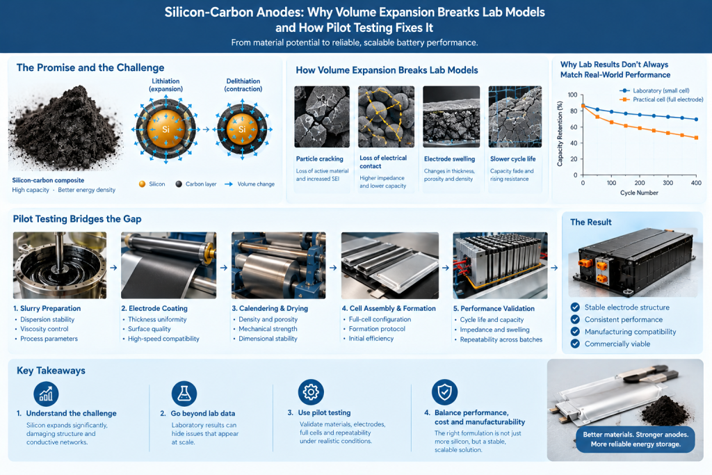
Silicon-carbon anodes are attracting significant attention in lithium-ion battery development because silicon can store substantially more lithium per unit mass than conventional graphite. By combining silicon with conductive carbon structures, battery developers aim to increase anode capacity while maintaining acceptable electrical conductivity, mechanical integrity, and cycle life.
However, the potential of silicon-carbon anodes comes with a major engineering challenge: silicon undergoes substantial volume changes during lithiation and delithiation. These repeated changes can damage the electrode structure, disrupt conductive pathways, weaken particle contacts, and accelerate capacity degradation.
Laboratory tests can identify promising materials, but they do not always predict how a silicon-carbon anode will behave in a practical electrode or commercial cell. Small electrodes, limited test durations, carefully controlled conditions, and simplified cell configurations may conceal failure mechanisms that become significant during scale-up.
Pilot testing helps bridge this gap. By reproducing more realistic mixing, coating, drying, calendering, cell assembly, and cycling conditions, developers can determine whether a silicon-carbon formulation can deliver repeatable performance beyond the laboratory.
This article explains why volume expansion challenges laboratory models, which failure mechanisms matter most, and how pilot-scale validation can improve the path from material development to commercial battery production.
1. Why Silicon-Carbon Anodes Are Different from Conventional Graphite Anodes
Graphite remains a widely used commercial anode material because of its established manufacturing processes, relatively stable structure, and predictable electrochemical behavior.
Silicon offers a different opportunity. It can accommodate much more lithium than graphite, creating the potential for higher anode capacity and improved cell-level energy density.
However, silicon’s lithium-storage mechanism involves significant structural changes.
During lithiation, lithium enters the silicon structure and causes it to expand. During delithiation, some of this volume change reverses. Repeated cycling can create mechanical stress within particles and across the electrode.
The magnitude of the problem depends on the silicon form, particle size, morphology, composite structure, state of charge, and cycling conditions. Different silicon materials therefore cannot be assumed to exhibit identical expansion behavior.
Silicon-carbon composites are designed to manage these challenges by combining silicon with carbon materials that may provide electrical conductivity, structural support, and space to accommodate expansion.
Possible architectures include:
- Silicon particles embedded in a carbon matrix.
- Silicon deposited on or integrated with porous carbon.
- Silicon-carbon composites containing graphite.
- Silicon-containing particles with engineered carbon coatings.
- Hybrid anodes incorporating conductive carbon additives such as carbon black or carbon nanotubes.
Each architecture presents different trade-offs in capacity, mechanical stability, first-cycle efficiency, processability, and cost.
The central engineering question is not simply how much silicon a material contains. It is whether the complete electrode can maintain sufficient electrical contact and structural integrity throughout repeated cycling.
2. How Volume Expansion Damages the Anode
Volume expansion affects silicon-carbon anodes at multiple structural levels, from individual particles to the complete electrode.
2.1 Particle cracking and structural damage
As silicon expands and contracts, internal stress can develop within particles. Depending on particle size, morphology, composition, and mechanical properties, this stress may lead to cracking or fragmentation.
Cracking can expose fresh silicon surfaces to the electrolyte, causing additional interfacial reactions and consuming lithium to form new solid-electrolyte interphase (SEI) material.
The resulting effects may include:
- Loss of active lithium.
- Increased irreversible capacity.
- Additional electrolyte consumption.
- Growth of interfacial resistance.
- Progressive deterioration of electrochemical performance.
Carbon coatings and engineered composite structures can help mitigate some of these effects, but their effectiveness depends on whether they remain sufficiently intact and conductive during cycling.
2.2 Loss of electrical contact
An electrode needs a continuous network connecting active particles to the current collector.
When silicon particles expand and contract, they can move relative to neighboring particles, carbon additives, and the binder network. Repeated mechanical changes may weaken these connections.
A particle may remain chemically capable of storing lithium but become partially or completely disconnected from the conductive network.
This distinction is important: active-material capacity and usable electrode capacity are not the same thing.
A silicon-carbon powder may demonstrate high capacity in an optimized laboratory configuration, yet a practical electrode may fail to access the same capacity if its conductive network cannot accommodate repeated structural changes.
2.3 Electrode swelling and thickness changes
Particle-level expansion accumulates across the electrode.
As the silicon-containing active material expands, electrode thickness and porosity can change. The resulting mechanical stress can affect the binder, conductive network, current-collector interface, and surrounding cell components.
In a practical battery, electrode swelling may also influence stack pressure, pouch thickness, cell dimensions, and mechanical integration.
The impact depends on the silicon fraction, electrode density, porosity, degree of lithiation, formulation, and cell design.
Consequently, expansion measured in a material powder cannot directly predict the dimensional behavior of a finished electrode or battery cell.
2.4 SEI growth and declining first-cycle efficiency
Silicon’s changing surface area can complicate the formation and stability of the SEI, a passivation layer that forms on the anode during initial cycling.
When new surfaces are exposed, additional electrolyte decomposition may occur. This consumes cyclable lithium and can reduce first-cycle Coulombic efficiency.
In a full cell, lithium consumed by the anode is not an unlimited resource. Lower initial efficiency can reduce the lithium available for subsequent cycling, potentially affecting usable capacity and energy density.
Developers may use engineered coatings, electrolyte additives, prelithiation, or other approaches to improve efficiency. However, each solution introduces its own process, safety, compatibility, and cost considerations.
A formulation that performs well in a half-cell test may therefore behave differently when paired with a practical cathode in a full cell.
3. Why Laboratory Models Often Fail to Predict Practical Performance
Laboratory testing is essential for screening materials and understanding mechanisms. The problem arises when laboratory results are treated as direct predictions of commercial-cell performance.
Several differences can explain the gap.
3.1 Small electrodes conceal mechanical limitations
Laboratory electrodes are often relatively small and may use carefully controlled coating and assembly conditions.
At this scale, local defects or nonuniformities may have limited influence on the measured result. In a larger electrode, the same defect population can create more opportunities for nonuniform current distribution, local stress concentration, and progressive degradation.
A larger coated area also introduces additional process variability, including coating-thickness differences, local loading variation, edge effects, and drying nonuniformity.
Pilot testing helps determine whether the formulation remains robust across representative electrode dimensions.
3.2 Half-cells do not reproduce full-cell lithium inventory constraints
Silicon-carbon materials are frequently evaluated in lithium-metal half-cells because they are useful for studying anode capacity, voltage behavior, and early-cycle degradation.
However, a lithium-metal counter electrode provides a different lithium reservoir from a practical cathode.
In a full cell, lithium lost through SEI growth and other irreversible processes reduces the cyclable lithium inventory. The cathode’s capacity, lithium inventory, electrode balancing, and operating window all influence the final result.
As a result, half-cell capacity retention alone cannot establish commercial full-cell energy density or cycle life.
A more complete validation program should progress from material screening to practical electrodes and then to representative full-cell configurations.
3.3 Low areal loading can hide transport limitations
Laboratory electrodes may use lower areal loading than commercial designs.
Lower loading can shorten ion-transport distances and reduce some gradients in concentration and reaction rate. A thicker electrode with higher areal capacity introduces additional transport constraints.
Silicon-carbon formulations must therefore be evaluated at relevant electrode loading, thickness, porosity, and density.
The key question is whether the material retains acceptable performance when the electrode is designed for practical energy density rather than only for convenient laboratory testing.
3.4 Laboratory formation may not represent manufacturing formation
The initial charging and discharging process, known as formation, influences SEI development and early-cell behavior.
Formation protocols can differ in current, temperature, rest periods, pressure, and cycle sequence. These conditions may affect first-cycle efficiency, impedance, and subsequent cycling.
A silicon-carbon formulation optimized under one formation protocol may not deliver identical performance under another.
Pilot-scale work helps establish a repeatable formation procedure and determine whether the resulting performance is compatible with the intended manufacturing process.
3.5 Short tests may miss cumulative degradation
Some failure mechanisms develop gradually.
Early cycles may show high capacity and acceptable Coulombic efficiency even while small structural changes accumulate. As cycling continues, electrical contact loss, SEI growth, electrode swelling, and impedance increase may become more pronounced.
A short test can therefore rank materials incorrectly if the intended application requires long service life.
Validation should combine early-cycle indicators with longer-term cycling and appropriate diagnostic measurements. The duration and test conditions should reflect the intended use case and the maturity of the development program.
4. The Role of Carbon Materials in Managing Silicon Expansion
Carbon materials can play several important roles in silicon-carbon anodes, but their effectiveness depends on architecture, dispersion, interfaces, and processing.
4.1 Carbon matrices and coatings
Carbon matrices may provide space for silicon expansion and help maintain electrical connectivity. Carbon coatings may also influence interfacial reactions between silicon and the electrolyte.
However, a carbon structure that is too dense may not provide sufficient expansion accommodation, while a structure that is too porous may reduce volumetric energy density or increase electrolyte demand.
The optimal design depends on the balance between mechanical stability, accessible capacity, electrolyte compatibility, and electrode packing.
4.2 Graphite as a capacity and structure-balancing component
Graphite can be blended with silicon-carbon materials to balance capacity, processability, and electrode behavior.
The appropriate silicon fraction depends on the target energy density, acceptable swelling, first-cycle efficiency, cycle life, and manufacturing capability.
Increasing silicon content may improve anode-level capacity, but it can also intensify expansion-related challenges and increase the demand on the binder and conductive network.
The highest silicon content is therefore not automatically the best commercial formulation.
4.3 Carbon nanotubes for conductive network reinforcement
Carbon nanotubes (CNTs) have a high aspect ratio and can form connected conductive networks at relatively low loading in suitable formulations.
In silicon-carbon electrodes, CNTs may be evaluated as part of a conductive-additive system intended to maintain electrical pathways as active particles change volume.
Potential benefits include improved network connectivity and reduced dependence on direct contact between individual active-material particles.
Nevertheless, CNT performance depends on dispersion quality, bundle size, surface chemistry, loading, and compatibility with the binder and slurry process.
Poorly dispersed CNTs can form agglomerates, increase slurry viscosity, complicate coating, and create nonuniform conductive regions. A network that works well in a laboratory slurry may not transfer directly to larger production batches.
Pilot validation must therefore evaluate both electrical performance and processability.
4.4 Graphene and hybrid conductive networks
Graphene may also be investigated as a conductive component or as part of a hybrid network combining CNTs, carbon black, graphite, or other conductive materials.
Different carbon structures can provide complementary conductive pathways. For example, plate-like and one-dimensional structures may interact differently with active particles and binder networks.
However, hybrid networks introduce additional formulation variables, including relative loading, dispersion sequence, rheology, drying behavior, and cost.
The relevant objective is not to maximize the number of carbon additives. It is to achieve reliable electrical connectivity at an acceptable total loading and manufacturing cost.
5. Why Binder and Electrode Formulation Matter as Much as the Active Material
Silicon-carbon performance cannot be understood by examining the active material alone.
The binder must maintain adhesion and cohesion while accommodating repeated changes in particle and electrode dimensions. Conductive additives must maintain electrical pathways. The electrolyte must support stable interfacial behavior, and the electrode architecture must provide appropriate porosity and transport properties.
5.1 Binder selection
Conventional graphite electrode formulations may not provide the same mechanical performance when the silicon fraction increases.
Depending on the material and design, developers may investigate water-based binders, carboxymethyl cellulose (CMC)-based systems, styrene-butadiene rubber (SBR), polyacrylic acid (PAA), or other binder approaches.
Each option has different adhesion, elasticity, swelling, processing, and compatibility characteristics.
The correct selection depends on the silicon architecture, electrode formulation, solvent system, drying conditions, and cell requirements.
5.2 Slurry rheology and coating quality
High-surface-area carbon additives and silicon-containing materials can change slurry viscosity, yield behavior, dispersion stability, and drying response.
These properties influence coating uniformity, edge quality, surface defects, and the ability to manufacture electrodes at practical speeds.
A formulation with excellent electrochemical performance but unstable slurry behavior may be unsuitable for production.
5.3 Calendering and porosity
Calendering compresses the dried electrode to achieve a target density and porosity.
For silicon-carbon anodes, the relationship between electrode density, available expansion space, ionic transport, electronic conductivity, and mechanical stress is especially important.
Excessive compaction may limit the free volume available for expansion or impair transport, while insufficient compaction may reduce volumetric energy density and weaken structural consistency.
Pilot trials should therefore examine how calendering conditions affect both initial electrode properties and subsequent cycling behavior.
6. How Pilot Testing Reveals Problems Hidden by Laboratory Models
Pilot testing provides a controlled environment for evaluating the complete electrode manufacturing process at a scale more representative of commercial production.
It does not eliminate the need for laboratory science. Instead, it tests whether laboratory-derived assumptions remain valid under practical conditions.
6.1 Reproducing the electrode manufacturing process
A representative pilot process should include the relevant steps, such as:
- Raw-material inspection and weighing.
- Slurry preparation and dispersion.
- Mixing under controlled conditions.
- Electrode coating.
- Drying and solvent or moisture control.
- Calendering and density adjustment.
- Slitting, cutting, and electrode handling.
- Cell assembly and formation.
The exact process depends on the electrode chemistry and manufacturing route.
Each stage can influence the final electrode. For example, changes in mixing energy can affect CNT dispersion, drying can influence binder distribution, and calendering can change porosity and mechanical stress.
Recording these parameters allows developers to link process conditions to electrode properties and cell performance.
6.2 Testing at practical areal loading
Pilot electrodes should be produced at loading levels relevant to the intended cell design.
This makes it possible to evaluate whether the silicon-carbon formulation retains acceptable coating quality, adhesion, transport behavior, and electrochemical performance at realistic thicknesses.
Testing multiple loading levels can also reveal the point at which a promising formulation becomes difficult to process or loses performance.
6.3 Measuring electrode expansion
Expansion should be assessed using a defined method under controlled conditions.
Depending on the development objective, measurements may include:
- Electrode thickness before and after cycling.
- Thickness change at specified states of charge.
- Cell or pouch swelling during cycling.
- Dimensional change after storage or aging.
- Correlation between expansion and capacity retention.
Measurements should account for the test configuration, stack pressure, state of charge, temperature, and measurement timing.
Free expansion of an isolated material is not directly equivalent to thickness change in a constrained electrode stack. Consistent measurement conditions are therefore essential when comparing formulations.
6.4 Evaluating mechanical and electrical integrity
Pilot testing can help determine whether the electrode remains cohesive and conductive after repeated cycling.
Useful diagnostic approaches may include:
- Electrode adhesion and cohesion tests.
- Cross-sectional imaging and microscopy.
- Surface and thickness uniformity measurements.
- Impedance analysis.
- Post-mortem inspection of cycled electrodes.
- Examination of particle cracking and interfacial degradation.
These methods provide complementary information. No single measurement can fully explain the failure mechanism, so results should be interpreted together.
6.5 Testing representative full cells
After material and electrode screening, the most promising formulations should be evaluated in full cells that reflect the intended application.
Relevant parameters include cathode chemistry, anode-to-cathode capacity ratio (N/P ratio), electrolyte quantity, electrode loading, formation protocol, stack pressure, and operating window.
The full-cell design determines how anode expansion, lithium inventory loss, and impedance growth translate into usable energy and cycle life.
Pilot testing should therefore evaluate the anode as part of the complete cell rather than treating it as an isolated material.
7. A Practical Pilot Validation Framework
A structured validation program helps teams make decisions based on evidence rather than relying on a single headline capacity value.
Stage 1: Define the target application
Establish the required energy density, power capability, cycle life, operating temperature, charging conditions, and dimensional constraints.
Identify the relevant failure modes and agree on acceptance criteria before testing begins.
Stage 2: Characterize the silicon-carbon material
Measure the properties needed to understand material behavior, such as composition, particle-size distribution, morphology, surface characteristics, and relevant electrochemical indicators.
Select tests based on the material architecture and the development objective.
Stage 3: Screen formulations in laboratory cells
Compare silicon fraction, conductive-additive systems, binder chemistry, and other formulation variables.
Use laboratory testing to eliminate weak candidates and identify promising combinations. Interpret half-cell results as screening evidence rather than direct commercial-cell predictions.
Stage 4: Develop pilot electrode processing
Transfer the selected formulations into a representative slurry and coating process.
Optimize mixing, coating, drying, and calendering while monitoring viscosity, coating quality, loading uniformity, adhesion, density, and porosity.
Stage 5: Evaluate expansion and structural stability
Measure electrode and cell dimensional changes under defined conditions. Relate expansion to mechanical integrity, impedance, capacity retention, and other relevant performance indicators.
Stage 6: Validate full-cell performance
Assemble representative full cells and evaluate initial efficiency, capacity, cycling, rate capability, impedance evolution, and swelling as appropriate.
Use consistent protocols and comparable cell designs when evaluating alternatives.
Stage 7: Assess repeatability across batches
Repeat the process using multiple material batches or pilot runs.
Investigate variation in raw-material characteristics, slurry behavior, coating quality, electrode properties, and electrochemical results.
Stage 8: Confirm manufacturability and economics
Assess material utilization, production yield, processing time, energy consumption, quality-control requirements, and cost per usable unit of cell capacity.
Proceed to broader scale-up only when the technical and manufacturing evidence supports the next stage.
8. Key Metrics for Silicon-Carbon Anode Pilot Testing
The most useful metrics depend on the target cell and development stage. A balanced test program should cover material behavior, electrode manufacturing, cell performance, and commercial feasibility.
| Evaluation area | Example metrics | Why it matters |
|---|---|---|
| Material properties | Composition, particle size, morphology | Helps identify material variability |
| Electrochemical performance | Specific capacity, Coulombic efficiency, capacity retention | Measures lithium-storage performance and degradation |
| Electrode quality | Areal loading, thickness, density, porosity, adhesion | Confirms manufacturing consistency |
| Expansion behavior | Electrode thickness change, cell swelling | Assesses dimensional stability |
| Electrical and interfacial behavior | Impedance evolution, conductivity where relevant | Helps diagnose contact loss and interfacial degradation |
| Processability | Slurry viscosity, dispersion stability, coating defects | Indicates production compatibility |
| Full-cell performance | Usable energy, rate capability, cycle life | Evaluates application-level results |
| Manufacturing economics | Yield, material consumption, processing cost | Determines commercial viability |
The results should be interpreted together. For example, lower electrode expansion is not automatically beneficial if it is achieved by reducing silicon content so much that the required capacity target is no longer met.
Similarly, high initial capacity may have limited value if first-cycle efficiency, cycle life, or production yield is poor.
The aim is to find a balanced operating window that satisfies the application’s technical and commercial requirements.
9. Common Mistakes During Silicon-Carbon Scale-Up
Mistake 1: Ranking materials by initial capacity alone
Initial capacity does not capture irreversible lithium loss, long-term degradation, or the impact of expansion on full-cell performance.
Better approach: Evaluate capacity together with first-cycle efficiency, swelling, impedance, and cycle-life indicators.
Mistake 2: Using half-cell results as a direct predictor of commercial cells
Half-cells do not reproduce the lithium inventory, cathode constraints, and electrode balancing of a practical full cell.
Better approach: Use half-cells for screening, then validate promising formulations in representative full-cell configurations.
Mistake 3: Increasing silicon content without redesigning the electrode
Higher silicon content may increase anode capacity but can intensify expansion, lithium loss, and mechanical stress.
Better approach: Optimize silicon fraction together with binder, conductive network, porosity, loading, and cell design.
Mistake 4: Ignoring slurry and coating behavior
An electrochemically promising formulation may be difficult to disperse, coat, dry, or calender consistently.
Better approach: Include processability and electrode-quality metrics from the early pilot stages.
Mistake 5: Measuring swelling without controlling test conditions
Expansion values may differ depending on state of charge, pressure, temperature, cell configuration, and measurement timing.
Better approach: Define a consistent protocol and compare like-for-like samples.
Mistake 6: Scaling up before establishing repeatability
A successful pilot batch does not demonstrate that the formulation will remain stable across future production runs.
Better approach: Validate multiple representative batches and establish practical material and process-control limits.
10. Balancing Performance, Cost, and Commercial Readiness
Silicon-carbon anodes must compete on more than active-material capacity.
The commercial value depends on how much additional usable energy the formulation delivers at the cell or pack level, how long that performance lasts, and whether the material can be manufactured reliably.
Cost considerations include:
- Silicon-carbon material price.
- Conductive additives and binder consumption.
- Slurry preparation and processing requirements.
- Drying and calendering energy.
- First-cycle lithium loss and any mitigation strategy.
- Production yield and rejected electrodes.
- Cell formation time and qualification costs.
- Cycle life and usable energy over the product’s lifetime.
A formulation with higher theoretical capacity may not provide the best economics if it requires expensive processing, exhibits low first-cycle efficiency, or degrades rapidly.
Conversely, a moderate silicon fraction may deliver a more attractive commercial result if it offers meaningful energy improvement while maintaining manufacturability and durability.
Pilot data helps quantify these trade-offs and supports decisions about whether to optimize the current formulation, change the electrode architecture, or reconsider the target application.
Conclusion
Silicon-carbon anodes offer a promising route to higher-capacity lithium-ion batteries, but silicon’s repeated volume changes create mechanical, interfacial, and manufacturing challenges that cannot be fully understood through material capacity measurements alone.
Laboratory tests can identify promising compositions, yet small electrodes, half-cell configurations, low areal loading, and short test durations may conceal limitations that emerge during practical electrode production and full-cell cycling.
Pilot testing addresses this gap by evaluating the complete chain from material dispersion and electrode processing to expansion behavior, full-cell performance, batch repeatability, and manufacturing economics.
For battery developers, the objective is not simply to maximize silicon content or initial capacity. It is to create an electrode that balances usable capacity, first-cycle efficiency, structural stability, cycle life, and production consistency.
The path from silicon-carbon potential to commercial battery performance depends on realistic electrode design, controlled manufacturing, and pilot validation that connects material behavior to full-cell results.
Frequently Asked Questions
Why does silicon expand during battery charging?
During lithiation, lithium enters the silicon structure and changes its composition and volume. The degree of expansion depends on the silicon form, lithiation level, particle structure, and operating conditions.
How does silicon expansion reduce battery cycle life?
Repeated expansion and contraction can cause particle cracking, loss of electrical contact, electrode deformation, and repeated SEI formation. These mechanisms may consume cyclable lithium and increase impedance over time.
Why can silicon-carbon anodes perform well in laboratory tests but poorly in practical cells?
Laboratory tests may use small electrodes, lower areal loading, simplified cell configurations, or short cycling protocols. Practical cells introduce additional constraints involving lithium inventory, electrode thickness, mechanical pressure, processing variability, and full-cell design.
Can CNTs or graphene prevent silicon expansion?
No. CNTs and graphene may help maintain conductive pathways or contribute to composite structures that accommodate some mechanical change, but they do not automatically eliminate silicon expansion. Their benefits depend on material architecture, formulation, dispersion, and processing.
What should be measured during pilot testing?
Relevant metrics include first-cycle Coulombic efficiency, capacity retention, electrode thickness change, cell swelling, impedance, electrode adhesion, coating uniformity, slurry processability, and full-cell performance. The exact test plan should reflect the intended application.
How does pilot testing improve silicon-carbon anode development?
Pilot testing reveals whether laboratory formulations remain processable and repeatable at more realistic electrode dimensions and loading levels. It also helps connect manufacturing variables to expansion, electrochemical degradation, and production cost.
Is a higher silicon content always better?
No. Higher silicon content may increase anode capacity but can also intensify expansion, lithium loss, mechanical stress, and processing challenges. The best formulation balances usable energy, durability, manufacturing requirements, and cost.