
High-Temperature Graphene Heating Elements: Substrate Selection, Electrical Insulation, and Reliability Testing
Graphene-based heating elements have attracted increasing attention in industrial heating, electronic thermal management, laboratory equipment, and high-temperature process applications.
Their electrical conductivity, thin-film structure, and potential for uniform Joule heating make graphene-based materials interesting candidates for next-generation heating technologies.
However, developing a high-temperature graphene heating element involves much more than selecting a conductive graphene material.
The substrate must withstand the target operating temperature, the electrical insulation system must remain stable, and the electrodes and interfaces must maintain reliable electrical contact during repeated thermal cycling.
In practical applications, the maximum operating temperature of a heating element is determined by its complete material and structural system rather than by the temperature resistance of graphene alone.
This article examines the key engineering considerations involved in designing high-temperature graphene heating elements, with a focus on substrate selection, electrical insulation, interface stability, and reliability testing.
1. How Graphene Heating Elements Generate Heat
Graphene heating elements generally operate through the Joule heating effect.
When an electrical current passes through a conductive graphene-based layer, electrical energy is converted into thermal energy.
The basic relationship is:
[
P=VI=I^2R=\frac{V^2}{R}
]
Where:
- (P) is electrical power
- (V) is applied voltage
- (I) is electrical current
- (R) is electrical resistance
The resulting heat is transferred through the surrounding structure by conduction, convection, and thermal radiation.
Depending on the product architecture, a graphene heating element may consist of:
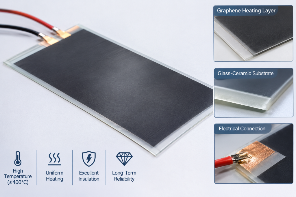
- A supporting substrate
- A graphene-based conductive heating layer
- Electrical electrodes or busbars
- An insulating layer or protective coating
- Electrical connection terminals
- Mechanical supports and an enclosure
Each component performs a different function.
The graphene layer generates heat, while the substrate provides mechanical support and influences heat distribution. Electrodes deliver electrical current, and the insulation system prevents unwanted current leakage or electrical breakdown.
At elevated temperatures, the stability of every component becomes increasingly important.
2. Substrate Selection for High-Temperature Graphene Heating
Substrate selection is one of the most important decisions in high-temperature heater development.
The substrate must provide mechanical stability, suitable thermal properties, electrical insulation where required, and compatibility with the graphene heating layer and electrode materials.
Different substrate materials offer different advantages and limitations.
2.1 Glass and Glass-Ceramic Substrates
Glass and glass-ceramic materials are attractive options for planar graphene heating elements.
Potential advantages include:
- Smooth surfaces for thin-film deposition
- Good electrical insulation
- Relatively uniform surface heating
- Compatibility with certain coating and printing processes
- Potential for integrated protective layers
Glass-ceramic substrates can offer improved thermal stability compared with many conventional glass materials.
However, the actual performance depends on the specific composition and manufacturing process.
Important considerations include:
Thermal expansion compatibility
The thermal expansion coefficients of the substrate, conductive layer, electrodes, and protective coatings should be sufficiently compatible.
Large differences can generate internal stress during heating and cooling, potentially causing cracking, delamination, or electrode failure.
Thermal shock resistance
Rapid temperature changes can produce significant thermal gradients.
The substrate must withstand the intended heating and cooling cycles without developing cracks or losing dimensional stability.
Maximum service temperature
The softening point, transformation behavior, crystallization characteristics, and long-term structural stability of the selected glass or glass-ceramic must be considered.
A material’s short-term temperature tolerance should not automatically be treated as its continuous operating temperature.
2.2 Alumina Ceramic Substrates
Alumina ceramics are widely used in electrical and thermal applications because of their electrical insulation and high-temperature stability.
Potential advantages include:
- High electrical resistivity
- Good dimensional stability
- High-temperature resistance
- Established ceramic manufacturing processes
- Availability in different thicknesses and geometries
Alumina can be suitable for graphene-based heating structures where electrical insulation and structural stability are priorities.
Nevertheless, surface roughness, metallization compatibility, thermal expansion, and bonding methods must be evaluated.
The ceramic surface may also require preparation before applying a graphene-based conductive coating.
2.3 Aluminum Nitride and Other Advanced Ceramics
Aluminum nitride (AlN) offers relatively high thermal conductivity combined with electrical insulation.
This makes it interesting for applications requiring controlled heat transfer while maintaining electrical isolation.
However, its cost, processing requirements, surface preparation, and interface compatibility may make it less suitable for some large-area heating products.
Other ceramic materials may also be considered depending on the required temperature, thermal conductivity, electrical insulation, and mechanical properties.
2.4 Metal Substrates with Electrical Insulation Layers
Metal substrates can provide mechanical strength and efficient heat spreading.
However, electrically conductive substrates introduce additional insulation requirements.
A typical structure may include:
- Metal support
- Electrically insulating dielectric layer
- Graphene-based heating layer
- Electrode system
- Protective surface layer
The dielectric layer must maintain sufficient electrical isolation at the actual operating temperature.
Its thermal conductivity, thickness, adhesion, dielectric strength, and thermal expansion compatibility all influence performance.
Metal-supported structures may be useful where mechanical durability and heat spreading are important, but insulation failure can create serious electrical safety risks.
Substrate Comparison
| Substrate | Main advantages | Main engineering considerations |
|---|---|---|
| Glass | Smooth surface, electrical insulation | Softening, thermal shock, long-term stability |
| Glass-ceramic | Potentially strong thermal stability | Composition-specific thermal behavior |
| Alumina | High-temperature insulation | Surface finish, thermal expansion, bonding |
| Aluminum nitride | High thermal conductivity and insulation | Cost, processing, interface compatibility |
| Metal with dielectric layer | Mechanical strength and heat spreading | Dielectric reliability and interface aging |
There is no universally optimal substrate. Selection should be based on the complete heater design and its intended operating environment.
3. Electrical Insulation: A Critical Requirement at High Temperatures
Electrical insulation becomes more challenging as operating temperature increases.
Materials that perform well at room temperature may exhibit reduced resistivity, changes in dielectric strength, or accelerated degradation under prolonged thermal exposure.
For graphene heating elements, insulation should be evaluated at the component and system levels.
3.1 Insulation Between the Heating Layer and the Support Structure
When a conductive graphene layer is deposited directly onto an insulating ceramic or glass substrate, the substrate may provide the primary electrical isolation.
However, when a metal support is used, an additional dielectric layer is generally required.
The insulation system should prevent electrical leakage from the heating layer to the support structure under normal operation and foreseeable fault conditions.
3.2 Edge and Terminal Insulation
Electrical failures do not necessarily occur in the central heating area.
The edges of the conductive layer, electrode connections, and terminal interfaces may experience higher electric-field concentrations.
Potential risks include:
- Surface leakage
- Electrical tracking
- Localized dielectric breakdown
- Insulation cracking
- Terminal overheating
- Short circuits caused by conductive contamination
Edge sealing and terminal insulation should therefore be treated as integral parts of the heater design.
3.3 High-Temperature Dielectric Materials
The selection of insulation materials depends on the operating temperature, electrical voltage, geometry, and environmental conditions.
Potential material categories include:
- High-temperature ceramic insulation
- Glass-based dielectric materials
- Alumina-based insulating structures
- Inorganic insulating coatings
- High-temperature electrical adhesives and sealing materials
Organic insulation materials require particular attention because many conventional polymers have relatively limited long-term thermal stability.
The insulation system should be qualified under actual operating conditions rather than selected only from room-temperature datasheets.
3.4 Electrical Insulation and Thermal Performance Must Be Balanced
Increasing insulation thickness may improve electrical isolation but can also increase thermal resistance.
Conversely, reducing insulation thickness may improve heat transfer while reducing dielectric safety margins.
The design should therefore balance:
- Dielectric strength
- Thermal conductivity
- Insulation thickness
- Mechanical adhesion
- Thermal expansion
- Long-term aging resistance
For high-temperature heating systems, electrical insulation and heat transfer should be optimized together.
4. Graphene Heating Layer: Composition and Interface Stability
The graphene-based conductive layer is the core heating component.
However, different graphene materials and coating technologies may behave differently under high-temperature operating conditions.
Potential approaches include:
- Graphene-based conductive inks
- Graphene oxide-derived conductive coatings
- Reduced graphene oxide films
- Graphene composite coatings
- Hybrid conductive structures incorporating other carbon materials
The final electrical and thermal properties depend on the material composition, coating method, film thickness, reduction or curing process, and contact structure.
4.1 Electrical Resistance Stability
A heating element must maintain a predictable resistance over its intended service life.
Resistance changes may result from:
- Thermal degradation
- Changes in conductive network connectivity
- Oxidation
- Microcracking
- Film delamination
- Electrode contact deterioration
Even a relatively small resistance change can influence power output and temperature distribution under constant-voltage or constant-current operation.
For example, under constant voltage, an increase in resistance reduces electrical power according to:
[
P=\frac{V^2}{R}
]
Therefore, resistance stability is directly related to heating performance.
4.2 Oxidation and Environmental Protection
Graphene-based conductive materials can undergo degradation under certain high-temperature oxidative environments.
The risk depends on the material structure, defects, surrounding atmosphere, operating temperature, and exposure duration.
Protective strategies may include:
- Inorganic protective coatings
- Glass-based encapsulation
- Ceramic protective layers
- Controlled-atmosphere operation
- Optimized substrate and interface design
However, protective coatings must be evaluated carefully.
A coating that protects the graphene layer may also introduce thermal stress, alter electrical contact conditions, or reduce heat transfer.
4.3 Electrode and Contact Reliability
The electrodes connect the heating layer to the external power supply.
At elevated temperatures, electrode materials and contact interfaces may experience oxidation, diffusion, stress, or degradation.
Important design considerations include:
- Electrode material selection
- Contact resistance
- Electrode geometry
- Bonding and joining methods
- Thermal expansion compatibility
- Terminal insulation
- Mechanical strain during thermal cycling
Electrode failure can lead to localized overheating even when the graphene heating layer itself remains relatively stable.
5. Thermal Uniformity and Temperature Control
A high-temperature heating element should not only reach the required temperature. It should also maintain an acceptable temperature distribution.
Non-uniform heating may result from:
- Variations in graphene film resistance
- Uneven coating thickness
- Inconsistent electrode contact
- Substrate thickness variation
- Localized heat loss
- Inadequate thermal spreading
- Poor mechanical mounting
5.1 Heating Layer Uniformity
The electrical resistance distribution across the active area should be controlled.
Non-uniform resistance can create localized hot spots or cold regions.
Mapping resistance and temperature distribution during prototype development helps identify these problems.
5.2 Electrode Geometry
Electrode placement and geometry influence current distribution.
An inappropriate electrode design may create higher current density near contact regions, leading to localized heating.
The design should consider the dimensions of the heating area, operating voltage, power requirement, and electrical resistance of the conductive layer.
5.3 Temperature Measurement
Infrared cameras and contact thermocouples can be used to evaluate temperature distribution.
However, infrared measurements require attention to surface emissivity, reflection, viewing angle, and calibration.
For glass or reflective surfaces, incorrect emissivity settings can lead to misleading temperature readings.
A reliable validation program should use calibrated measurement methods and clearly define where temperatures are measured.
6. Reliability Testing for High-Temperature Graphene Heating Elements
A prototype reaching its target temperature does not prove that it can operate reliably over an extended period.
Reliability testing should evaluate electrical, thermal, mechanical, and environmental stability.
6.1 Continuous High-Temperature Operation
Continuous operation testing evaluates whether the heating element can maintain its target temperature and electrical characteristics over a defined period.
Important parameters include:
- Applied voltage
- Current
- Electrical resistance
- Power consumption
- Surface temperature
- Temperature uniformity
- Resistance drift
- Visible material degradation
The test should be conducted at the intended operating temperature and under a representative mounting and environmental condition.
A short demonstration at an elevated temperature should not be used as evidence of long-term service life.
6.2 Thermal Cycling Tests
Thermal cycling evaluates the effects of repeated heating and cooling.
This is particularly important because different materials may expand and contract at different rates.
Testing should monitor:
- Cracks in the substrate
- Coating delamination
- Resistance changes
- Electrode degradation
- Insulation deterioration
- Changes in heating uniformity
The number of cycles, temperature range, heating rate, cooling rate, and dwell time should be defined according to the intended application.
6.3 Electrical Insulation Testing
Electrical insulation should be tested before and after high-temperature exposure.
Relevant evaluations may include:
- Insulation resistance
- Dielectric withstand voltage
- Leakage current
- Ground insulation integrity
- Surface tracking resistance, where applicable
Testing voltage and acceptance criteria should be selected according to the heater’s voltage rating, construction, applicable product standards, and intended operating environment.
Where the design includes a conductive metal support, grounding and fault protection should also be evaluated.
6.4 Temperature Uniformity Testing
Thermal imaging can identify hot spots and uneven heating.
A useful test should record:
- Maximum temperature
- Minimum temperature
- Average temperature
- Temperature variation across the active area
- Time required to reach thermal equilibrium
- Temperature stability during continuous operation
The acceptable temperature variation should be defined by the application.
6.5 Mechanical and Environmental Testing
Depending on the application, additional testing may include:
- Vibration resistance
- Mechanical shock
- Humidity exposure
- Oxidation resistance
- Protective coating integrity
- Terminal pull or connection strength
- Mounting and fastening stability
Not every heater requires every test. The validation plan should reflect the actual operating environment.
7. Common Failure Modes and Their Root Causes
Understanding failure mechanisms is essential for improving the reliability of graphene heating elements.
| Failure mode | Potential root cause | Recommended evaluation |
|---|---|---|
| Resistance increases | Film degradation, cracking, oxidation | Resistance monitoring and material inspection |
| Localized hot spots | Uneven coating or electrode contact | Thermal imaging and resistance mapping |
| Substrate cracking | Thermal stress or thermal shock | Thermal cycling and microscopy |
| Coating delamination | Poor adhesion or expansion mismatch | Adhesion and cross-section inspection |
| Electrical leakage | Insulation degradation or contamination | Insulation resistance and dielectric testing |
| Electrode failure | Oxidation, diffusion, or poor bonding | Contact resistance and interface analysis |
| Temperature instability | Resistance drift or control-system issues | Long-duration thermal testing |
The same visible failure can have several possible causes.
For example, a hot spot may result from a local increase in film resistance, poor electrode contact, or uneven heat dissipation.
Root-cause analysis should therefore combine electrical measurements, thermal imaging, and physical inspection.
8. A Practical Development and Validation Workflow
A systematic development process can reduce technical risk before moving to pilot production.
Stage 1: Define Application Requirements
Establish the intended operating conditions:
- Target operating temperature
- Maximum temperature
- Continuous or intermittent operation
- Heating area and geometry
- Supply voltage
- Required electrical power
- Heating and cooling time
- Operating atmosphere
- Expected service life
- Electrical safety requirements
The distinction between target temperature, maximum allowable temperature, and short-duration peak temperature is particularly important.
Stage 2: Select the Substrate and Insulation System
Evaluate glass, glass-ceramic, ceramic, and metal-supported structures.
The selection should consider temperature resistance, thermal expansion, dielectric performance, mechanical strength, thermal conductivity, and manufacturing compatibility.
Stage 3: Develop the Conductive Heating Layer
Select the graphene material system and coating process according to the intended temperature and electrical requirements.
Evaluate film resistance, thickness uniformity, adhesion, oxidation resistance, and compatibility with the substrate.
Stage 4: Integrate Electrodes and Connections
Design the electrode structure and terminal connections.
Evaluate contact resistance, current distribution, high-temperature stability, and insulation around the connection area.
Stage 5: Build and Evaluate Prototypes
Prototype testing should include:
- Electrical resistance measurement
- Power and current verification
- Heating rate measurement
- Temperature distribution mapping
- Continuous operation
- Initial thermal cycling
- Insulation testing
Stage 6: Conduct Reliability Validation
After the initial prototype performs as expected, conduct longer-duration testing under representative conditions.
The test plan should include defined acceptance criteria and failure analysis procedures.
Stage 7: Pilot Production and Repeatability
Before commercial production, verify that the manufacturing process can consistently reproduce the heating element.
Important controls include:
- Substrate incoming inspection
- Coating thickness and uniformity
- Electrical resistance distribution
- Electrode positioning
- Bonding quality
- Insulation integrity
- Final thermal performance
- Batch traceability
A reliable prototype is only the first step. Manufacturing repeatability is necessary for commercial adoption.
9. How to Define a Meaningful High-Temperature Service-Life Target
A common challenge in heating element development is the difference between a material’s temperature resistance and the product’s actual service life.
A graphene coating may retain certain properties after a short high-temperature exposure, but this does not establish the long-term reliability of the complete heating assembly.
For example, a heater designed for continuous operation at 350°C requires validation of:
- The graphene conductive layer
- The substrate
- The electrode system
- Electrical insulation
- Protective coatings
- Mechanical mounting
- Electrical terminals
Each component must remain functional under the same operating conditions.
A service-life target such as 5 or 10 years should be supported by an appropriate reliability program.
Accelerated aging can help identify degradation mechanisms, but it should not be used to claim a specific field lifetime without a validated correlation between accelerated testing and actual operating conditions.
The most useful approach is to establish measurable acceptance criteria, conduct representative long-duration testing, and update the reliability model as additional operating data becomes available.
10. Future Opportunities for High-Temperature Graphene Heating
Graphene-based heating technologies may offer opportunities in several industrial sectors.
Industrial Process Heating
Potential applications include localized heating, laboratory equipment, thermal processing, and compact heating assemblies.
Glass and Ceramic Heating Systems
Graphene-based conductive layers may be integrated into glass or ceramic structures for planar heating applications.
The substrate and protective system must be selected according to the required temperature and thermal cycling conditions.
Electronic and Thermal Management Equipment
Specialized heating elements may be used for temperature conditioning, anti-condensation, and controlled heating in electronic equipment.
Customized High-Temperature Components
For specialized equipment manufacturers, custom heating geometries and integrated thermal structures may provide opportunities to develop application-specific products.
Commercial success will depend on repeatable manufacturing, electrical safety, thermal performance, and verified operating life rather than graphene content alone.
Conclusion
High-temperature graphene heating elements are promising for specialized industrial heating applications, but their performance depends on the complete heater architecture.
Substrate selection determines much of the mechanical and thermal foundation. Electrical insulation protects the system under elevated temperatures, while electrode and interface design influence electrical stability and heat distribution.
Reliability testing must go beyond demonstrating that a prototype can reach a target temperature. Continuous operation, thermal cycling, insulation integrity, temperature uniformity, and manufacturing repeatability should all be evaluated.
The most effective development strategy is to treat the graphene layer, substrate, insulation, electrodes, and protective structure as one integrated heating system.
For manufacturers developing high-temperature graphene heaters, material selection and system-level validation are equally important steps toward reliable industrial commercialization.
Frequently Asked Questions
1. What substrate is best for high-temperature graphene heating elements?
There is no universal best substrate. Glass-ceramic, alumina, aluminum nitride, and metal-supported structures with dielectric insulation may all be considered. Selection depends on operating temperature, electrical insulation, thermal conductivity, mechanical requirements, and manufacturing compatibility.
2. Can graphene heating elements operate continuously above 300°C?
Potentially, depending on the graphene material, substrate, atmosphere, electrodes, insulation, protective layers, and overall structure. Continuous operation above 300°C must be demonstrated through system-level testing rather than inferred from the temperature resistance of the graphene material alone.
3. Why is electrical insulation important in high-temperature graphene heaters?
Electrical insulation prevents current leakage and short circuits. At elevated temperatures, dielectric properties may change, so insulation performance must be evaluated under representative thermal and electrical conditions.
4. What causes resistance drift in graphene heating elements?
Potential causes include oxidation, thermal degradation, changes in the conductive network, cracking, delamination, and electrode contact deterioration. Monitoring resistance during continuous operation and thermal cycling can help identify these mechanisms.
5. How should the reliability of a graphene heating element be tested?
A comprehensive program should include continuous high-temperature operation, thermal cycling, electrical insulation testing, temperature uniformity measurement, and relevant mechanical or environmental tests. Acceptance criteria should be defined before testing.
6. Does a successful high-temperature test prove a 10-year service life?
No. A short-duration test demonstrates performance under a particular test condition, not a specific long-term service life. Long-term claims require representative aging data, validated acceleration methods, and an understanding of the degradation mechanisms.