

Slot-Die Shims Adjustment: Customizing Electrode Striping for Specialized Energy Storage
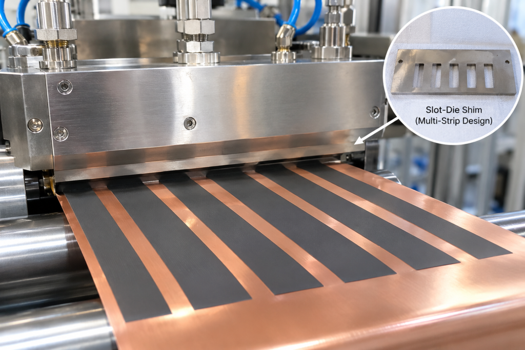
Electrode coating is one of the most important processes in lithium-ion and other advanced energy storage battery manufacturing. While conventional electrode production often uses continuous coating across a defined width, specialized battery designs may require more flexible coating patterns.
Examples include multi-strip electrode coating, intermittent coating, customized coating widths, uncoated lanes, and electrodes with different active material regions.
Slot-die shims provide a practical way to customize these coating patterns. By modifying the shim opening, width, spacing, and internal flow distribution, manufacturers can adapt a slot-die coating head to produce electrode strips with specific geometries.
For specialized energy storage applications, shim adjustment is not simply a mechanical modification. It involves fluid distribution, slurry rheology, coating uniformity, edge definition, and process stability.
This article explains how slot-die shims can be customized to control electrode striping and what manufacturers should consider when developing specialized coating configurations.
1. What Is a Slot-Die Shim?
A slot-die coating head typically consists of two die halves, an internal slurry distribution cavity, and a precision shim positioned between the die components.
The shim defines the coating gap and helps determine the geometry of the coating outlet.
Its design influences:
- Coating width
- Coating thickness
- Number of coating lanes
- Distance between adjacent strips
- Uncoated regions
- Edge geometry
- Slurry flow distribution
In a conventional single-slot configuration, the shim opening forms one continuous coating outlet. When the application requires multiple electrode strips, the shim can be designed with multiple openings separated by solid sections.
These openings allow slurry to flow through selected regions while blocking flow in other areas.
The resulting coating pattern can contain multiple parallel electrode strips on the same current collector.
2. How Shim Design Creates Multiple Electrode Strips
The basic principle of striping customization is to control where slurry can exit the die.
A customized shim may contain several independent openings or a continuous opening with strategically positioned blocking sections.
For example, a multi-strip configuration can be designed with:
- Three parallel coating lanes
- Four or more narrow electrode strips
- Different widths for individual strips
- Defined gaps between adjacent strips
- Uncoated margins along both edges
The geometry of the openings determines the initial coating pattern.
However, the final stripe dimensions also depend on slurry properties, coating speed, die-to-substrate distance, flow rate, and wetting behavior.
Key shim geometry parameters
Opening width
The opening width largely defines the nominal width of each coating strip. Narrower openings can produce narrower strips, but they may also increase sensitivity to particles, agglomerates, and flow imbalance.
Blocking-section width
The solid regions between openings create uncoated lanes. Their dimensions must account for the actual slurry flow behavior and possible lateral spreading after the slurry exits the die.
Opening length and outlet geometry
The shim opening and the geometry of the die outlet influence flow resistance and pressure distribution. Poorly balanced openings may cause different coating rates between strips.
Edge geometry
The shape and precision of the opening edges influence stripe boundaries. Burrs, machining defects, or uneven assembly can lead to irregular edges and local coating defects.
3. Customizing Electrode Striping for Different Battery Designs
Not all energy storage electrodes require the same coating pattern.
Shim customization can support several specialized configurations.
Multi-strip electrode coating
Multiple narrow electrode strips can be coated simultaneously across a single current collector.
This approach may be useful for specialized electrode formats, experimental cell architectures, and applications requiring multiple active material lanes.
The main challenge is maintaining consistent coating thickness and width across all strips.
Intermittent and segmented coating
Some electrode designs require coated and uncoated regions along the machine direction.
This pattern is commonly associated with current collector tabs, welding areas, and downstream electrode processing requirements.
It is important to distinguish cross-web striping from machine-direction intermittent coating. A shim can define cross-web coating lanes, but machine-direction patterning generally requires additional flow-control or process-control mechanisms, such as synchronized slurry interruption.
Different coating widths on the same substrate
Some development projects may require different coating widths or lane configurations on one current collector.
A customized shim can help create these geometries, provided the die’s internal distribution system can supply each opening consistently.
Uncoated safety or functional lanes
Certain specialized electrode designs may require uncoated regions for assembly, insulation, or other functional purposes.
The width and location of these regions should be determined by the cell design and downstream manufacturing requirements rather than by coating equipment limitations alone.
4. The Relationship Between Shim Geometry and Slurry Flow
A shim defines the outlet geometry, but it does not independently guarantee uniform coating.
The slurry must flow through each opening at a controlled and repeatable rate.
Several factors influence this behavior.
Slurry viscosity and rheology
Battery electrode slurries are generally non-Newtonian. Their apparent viscosity can change with shear rate, temperature, solids content, and formulation.
A slurry that flows well through a wide opening may behave differently when passed through several narrow openings.
High viscosity or poor dispersion can increase the risk of unstable flow, uneven strip formation, or partial blockage.
Flow resistance between coating lanes
Different opening widths create different hydraulic resistance.
If several openings share a common internal distribution cavity, the slurry may not distribute equally unless the die design and process parameters are properly matched.
This can result in:
- Different wet coating thicknesses between strips
- Uneven stripe widths
- Local flow instability
- Inconsistent coating edges
Pressure distribution
The pressure inside the die must support stable flow across all coating lanes.
A multi-opening shim can change the total outlet area and flow resistance. Therefore, the required slurry flow rate and operating pressure should be reassessed after changing the shim.
Wetting and edge behavior
After exiting the die, slurry interacts with the current collector surface.
Surface energy, substrate cleanliness, slurry formulation, and coating speed can affect the stability of stripe boundaries.
Even when the shim geometry is accurate, poor wetting behavior may cause spreading, edge irregularities, or merging between adjacent strips.
5. Important Parameters When Designing Customized Shims
A successful shim design starts with the electrode geometry and the intended production process.
The following parameters should be defined before manufacturing a customized shim.
| Design parameter | Main consideration |
|---|---|
| Number of strips | Required number of parallel coating lanes |
| Strip width | Target width of each active material region |
| Inter-strip gap | Required uncoated spacing between lanes |
| Edge margin | Distance from the outer coating lanes to the substrate edges |
| Shim thickness | Must match the die assembly and coating requirements |
| Opening geometry | Shape, length, and precision of each outlet |
| Material | Dimensional stability, corrosion resistance, and wear resistance |
| Manufacturing tolerance | Precision of openings and blocking sections |
The shim thickness should not be confused with the final wet coating thickness. The coating thickness is influenced by the complete coating system, including flow rate, coating speed, die geometry, and slurry properties.
6. Common Challenges in Multi-Strip Electrode Coating
Uneven coating thickness between strips
Different flow resistance across individual openings can produce different coating thicknesses.
This issue may require adjustments to the opening geometry, internal flow distribution, slurry flow rate, or coating conditions.
Irregular stripe edges
Poorly defined edges may result from shim machining defects, assembly gaps, slurry spreading, or unstable wetting.
Precision manufacturing and careful die assembly are essential.
Slurry accumulation and blockage
Narrow openings are more sensitive to particles, agglomerates, and dried slurry residues.
Proper slurry filtration, dispersion control, cleaning procedures, and maintenance are important for stable operation.
Stripe merging
When adjacent coating lanes are too close, slurry may spread laterally and connect neighboring strips.
The required gap must therefore be validated under actual coating conditions rather than determined only from the nominal shim dimensions.
Differences between the left and right sides
Uneven die assembly, pressure distribution, substrate alignment, or flow conditions can create asymmetry between coating lanes.
Inspection should cover the complete coating width, not only the center region.
7. How to Develop and Validate a Customized Shim
A practical development process should connect the customer’s electrode requirements with the actual coating equipment and slurry system.
Step 1: Define the coating pattern
Collect the required number of strips, individual strip widths, spacing, edge margins, substrate width, and coating direction.
A dimensioned drawing is preferable to a verbal description.
Step 2: Review the existing slot-die equipment
Confirm the die model, shim installation method, available coating width, internal manifold configuration, and compatible shim thickness.
Not every slot-die head can support every multi-strip arrangement simply by changing the shim.
Step 3: Review slurry characteristics
Relevant information includes:
- Active material and conductive additive system
- Binder and solvent system
- Solid content
- Viscosity and rheological behavior
- Particle size and dispersion quality
- Temperature and storage conditions
These factors help determine whether the proposed openings are suitable for the slurry.
Step 4: Design and manufacture the shim
The shim should be designed according to the target coating geometry and the equipment’s mechanical and hydraulic constraints.
Precision cutting, dimensional inspection, edge quality, and flatness should be checked before installation.
Step 5: Conduct trial coating
Initial trials should focus on flow stability and stripe formation.
The coating should be inspected for:
- Actual strip width
- Gap width
- Wet coating thickness
- Edge definition
- Thickness consistency between lanes
- Surface defects
- Stability over time
Step 6: Dry and inspect the electrodes
Wet coating appearance alone is not sufficient.
After drying, evaluate coating thickness, loading consistency, edge quality, adhesion, and any cracking or delamination.
Where relevant, calendering and downstream processing should also be included in validation.
Step 7: Confirm repeatability
A successful first trial does not automatically establish production readiness.
Repeat trials should confirm that the coating pattern remains stable across different batches and operating periods.
8. Why Customized Shim Solutions Matter for Specialized Energy Storage
As battery designs become more diverse, manufacturers may need electrode geometries that are not supported by standard coating configurations.
Customized shims can provide a relatively flexible way to modify coating patterns without redesigning the entire coating system.
Potential applications include:
- Specialized lithium-ion battery electrodes
- Sodium-ion battery development
- Experimental multi-lane electrode structures
- Customized electrode widths for pilot production
- Research and development of new cell architectures
- Small-batch manufacturing for specialized energy storage products
For pilot lines and research facilities, interchangeable shim configurations can also help evaluate different electrode layouts using the same basic coating equipment.
However, the economic benefit depends on equipment compatibility, shim manufacturing cost, setup time, cleaning requirements, and the number of coating configurations needed.
9. Practical Recommendations for Manufacturers
Before ordering a customized slot-die shim, manufacturers should prepare a complete technical requirement package.
At minimum, it should include:
- Slot-die manufacturer and model
- Existing shim dimensions and thickness
- Current collector material and width
- Required number of coating strips
- Target width of each strip
- Required uncoated gap dimensions
- Slurry formulation and rheological information
- Target coating loading or thickness
- Coating speed and operating conditions
- Required inspection and acceptance criteria
Providing these details helps the equipment or shim supplier evaluate whether the requested coating pattern can be achieved with the existing die structure.
It also reduces unnecessary trial-and-error during the development process.
Slot-die shim adjustment is an effective approach for customizing electrode striping in specialized energy storage manufacturing.
By modifying the number, width, and spacing of shim openings, manufacturers can create multi-strip coating patterns and customized uncoated regions for different electrode designs.
However, successful striping requires more than accurate shim dimensions. Slurry rheology, internal flow distribution, pressure balance, wetting behavior, die assembly, and downstream electrode processing all influence the final result.
The most reliable approach is to combine precise shim design with equipment compatibility review and systematic pilot validation.
For specialized battery development, customized shims can provide a practical route to greater coating flexibility while maintaining control over electrode quality and process repeatability.
Questions
1. Can a standard slot-die coating head produce multiple electrode strips?
In some cases, yes. A customized shim with multiple openings can create several coating lanes, provided the die’s internal distribution design and operating conditions support uniform flow.
2. Does shim thickness determine the final electrode coating thickness?
No. Shim thickness is an important die assembly parameter, but final coating thickness also depends on slurry flow rate, coating speed, die geometry, and slurry properties.
3. Can slot-die shims create uncoated gaps between electrode strips?
Yes. Solid sections between shim openings can block slurry flow and form uncoated lanes. The actual gap dimensions should be validated because slurry spreading and wetting behavior can affect the final pattern.
4. Can one customized shim produce different strip widths?
Yes. Individual openings can be designed with different widths. However, the resulting flow distribution must be evaluated to avoid differences in coating thickness between lanes.
5. Is a customized shim suitable for pilot-scale battery production?
It can be particularly useful for pilot-scale development, where manufacturers need to test different electrode geometries without replacing the complete slot-die coating system. Equipment compatibility and repeatability should be confirmed before production use.